heavy rainfall across modern developments presents a constant challenge for civil engineers and site planners trying to protect local communities from localised flooding. As concrete surfaces expand, natural drainage pathways disappear, forcing excessive volumes of surface water into aging municipal sewer networks. This article explores how combining a sub-surface attenuation tank with a precisely calibrated orifice plate creates a robust Sustainable Drainage System, commonly known as SuDS. By storing peak runoff during severe storms and releasing it at a controlled rate, ground engineers can prevent downstream surcharging and meet strict water authority limits. Drawing on over 30 years of hands-on installation experience, Catalogue Engineering breaks down the essential principles of flow control, highlighting practical methods to keep your SuDS infrastructure working reliably for decades.
Managing peak runoff on heavily developed sites often leads to severe design headaches for civil engineering teams. Strict discharge limits set by water authorities frequently conflict with spatial constraints on cramped modern plots.
Failing to control these flows properly causes immediate site flooding, severe structural delays, and costly regulatory fines from local water boards. Unplanned remedial work on poorly managed surface water systems rapidly eats into project budgets and burns through valuable labor hours.
Integrating a well-designed attenuation tank with a reliable flow-control mechanism offers a dependable surface water management strategy for modern sites. This proven SuDS approach holds back intense storm volumes temporarily, releasing water safely back into local networks at a stable, pre-approved rate.
KEY TAKEAWAYS
- Attenuation tanks store excess rainwater during heavy downpours to prevent immediate flooding across local streets.
- Orifice plates provide a simple, cost-effective method to throttle discharge rates and protect downstream infrastructure.
- Specialist installers with long-term sector experience ensure SuDS components meet strict regulatory standards without causing maintenance headaches.
Table of Contents
- How Orifice Plates Function Within the Tank Outlet Chamber
- Sizing Attenuation Storage Alongside Controlled Discharge Limits
- Preventing Blockages and Maintaining Flow Control Performance
- Best Practice Site Installation and Engineering Considerations
- Frequently Asked Questions around Attenuation Tank
Need Specialist Advice on attenuation tank?
Speak to our technical team today for tailored specifications, regulations compliance, and practical support.
How Orifice Plates Function Within the Tank Outlet Chamber
At the heart of any effective surface water drainage system lies the flow control chamber, where the orifice plate performs its essential work. By converting complex hydraulic forces into a predictable, passive restriction, this simple stainless-steel plate ensures that heavy rainfall does not overpower downstream drainage networks.
Hydraulic pressure and the role of hydrostatic head
An orifice plate restricts water flow by utilising the variable hydrostatic head created within the attenuation tank as it fills. As storm water accumulates in the storage volume, the increasing water depth generates greater pressure at the base of the chamber, forcing liquid through the central aperture at a precisely calculated rate.
This elegant mechanism relies entirely on natural physics rather than mechanical moving parts. The practical operation follows a predictable 3-step cycle during any severe rainfall event.
- Stormwater enters the attenuation storage unit, causing the internal water level to rise rapidly above the outlet invert.
- The increasing hydrostatic head creates higher pressure behind the plate, gradually increasing the velocity through the aperture while keeping the total discharge rate within safe, pre-agreed limits.
- As the storm passes and the tank empties, the head drops, reducing the flow naturally until the system returns to its dry-weather state.
Managing water movement within the chamber
The physical layout of the flow control chamber dictates how effectively the orifice plate maintains the desired discharge rate. Positioned on the outgoing pipework or mounted directly against the chamber wall, the plate creates a deliberate bottleneck that controls the pass-through volume.
Good design practices ensure that debris does not blind the central opening during peak operation. Installers typically fit a heavy-duty mesh screen or a sumped floor arrangement directly upstream of the plate. These simple additions catch grit, leaves, and trash before they reach the aperture, protecting the calculated hydraulic profile.
Emergency overflow and maintenance integration
A well-designed flow control chamber incorporates integrated bypass routes to manage extreme storms that exceed the standard design capacity. If an extraordinary weather event fills the attenuation tank past its maximum operating level, water safely spills over an internal weir wall situated above the primary plate.
This dual-action approach prevents localised flooding by offering a controlled emergency release route without compromising day-to-day operation. Access covers positioned directly above the plate allow site managers to inspect, clean, and clear the chamber using high-pressure jetting equipment. With over 30 years of hands-on industry experience, our installation teams ensure these chamber layouts remain accessible for long-term maintenance, protecting surrounding local areas from surface water flooding for decades.
| Control Configuration | Flow Regulation Mechanics | Silt and Blockage Risk | Maintenance Access Requirements | Best Application |
|---|---|---|---|---|
| Integral Hydro-Brake or Vortex Valve | Uses fluid dynamics to create a vortex, restricting flow without small apertures | Low risk due to larger clear openings than standard orifice plates | Requires standard manhole access with a bypass rope pull for clearing debris | Complex attenuation tank systems requiring precise discharge rates under variable heads |
| Wall-Mounted Fixed Orifice Plate | Static stainless steel plate fitted directly to the discharge wall inside the control chamber | Moderate to high risk if aperture size is under 100 mm diameter | Requires direct chamber entry for manual clearance or high-pressure jetting | Low-budget attenuation projects with consistent, larger design flow rates |
| Quick-Release Sliding Orifice Unit | Plate mounted within a vertical runner system, allowing easy removal from ground level | Moderate risk, but easily mitigated by lifting the plate to flush the system | Minimal risk entry needed as the plate lifts out from surface level guide rails | Deep attenuation tank chambers where confined space entry must be avoided |
| Sump-Integrated Orifice Unit with Screen | Orifice plate positioned below invert level, protected by a debris guard mesh | Low risk at the plate, but high risk of screen blinding if unmaintained | Regular surface inspections required to clear silt trap and screen face | Attenuated runoff from high-sediment areas like gravel car parks or industrial yards |
Sizing Attenuation Storage Alongside Controlled Discharge Limits
Balancing peak inflows with allowable site outflows requires a detailed understanding of civil engineering principles and local planning conditions. Getting this calculation right ensures your attenuation tanks hold precisely the right volume without over-specifying costly underground infrastructure.
Balancing greenfield runoff rates with site volume
Calculating your baseline greenfield runoff rate establishes the absolute maximum discharge speed permitted by local flood authorities. You must then size your attenuation tanks to store every drop of stormwater that exceeds this strict limit.
When peak rainfall hits a developed site, hard surfaces generate rapid surface runoff. Because an orifice plate mechanically restricts the flow out of the tank to match pre-development levels, the remaining volume backs up into the tank. Specialist installers evaluate historical meteorological data to accurately forecast these inflow volumes.
To establish the correct storage capacity for your development, follow these 3 core steps:
- Determine the greenfield runoff rate using standard industry software to set your maximum permissible discharge rate.
- Model a range of severe storm events to identify the peak volume of water arriving at the tank.
- Calculate the differential between peak incoming volume and restricted outgoing flow to establish your required tank storage capacity.
Performing accurate hydraulic calculations for orifice control
Accurate hydraulic calculation models predict how an orifice plate performs under varying head pressures as an attenuation tank fills. As water rises inside the tank, increased hydrostatic pressure forces water through the central aperture at a progressively faster rate.
Engineers must account for this variable discharge curve rather than assuming a static outflow speed. A tank half full exerts less driving pressure than a tank at maximum capacity, directly altering the discharge rate. Fine-tuning these calculations prevents premature site flooding during shorter, intense rainfall bursts.
Accounting for extreme storm events and climate resilience
Planning rules require attenuation systems to accommodate severe 1-in-100-year storm events alongside a dedicated allowance for climate change. Designing for these extraordinary weather patterns guarantees that your underground storage capacity prevents catastrophic surface flooding.
Incorporating a 40% allowance for climate resilience has become a standard requirement across most UK planning jurisdictions. If a storm exceeds predicted limits, well-designed systems include emergency high-level overflow routes to manage surplus water safely. Combining precise orifice plate sizing with robust attenuation tanks delivers long-term protection for the local area, protecting downstream communities for decades to come.
Preventing Blockages and Maintaining Flow Control Performance
Integrating an orifice plate with a stormwater attenuation tank offers a remarkably cost-effective approach to managing surface water run-off. However, because these systems rely on a precisely calibrated aperture to restrict peak flows, even minor blockages can cause severe upstream flooding or compromise downstream drainage networks.
Installing upstream silt traps and catchpits
Upstream catchpits and silt traps serve as your primary defense by capturing heavy sediment before it ever reaches the restricted aperture. Positioned directly prior to the attenuation tank outlet, these units drop water flow velocity, allowing suspended solids to settle at the base of a deep sump.
To maximise performance across long-term operations, site teams should implement a straightforward 3-step maintenance strategy
- Inspect the catchpit sump every 3 months during initial site commissioning to gauge localised silt accumulation rates.
- Vacuum out settled debris using standard suction tankers once silt levels reach 50% of the total sump capacity.
- Flush connecting pipework with low-pressure water jets to ensure smooth, unhindered hydraulic transport toward the tank.
By trapping grit and fine gravel early, you protect the restricted opening from abrasive wear while keeping the attenuation storage volume fully available for heavy rainfall events.
Incorporating robust debris screen protection
A well-designed debris screen acts as an essential physical barrier, preventing floating rubbish and organic leaf litter from blinding the central opening. Mounting a durable screen across the outlet face distributes incoming hydraulic pressure while keeping larger items well clear of the restricted aperture.
Choosing the right screen geometry is just as important as the orifice plate sizing itself. Side-mounted or angled screens offer significantly greater surface area than flat vertical panels, which helps maintain design flow rates even if partial leaf accumulation occurs during autumn storms. Specialist installers routinely specify removable, marine-grade stainless steel meshes that withstand constant damp conditions without corroding. This robust barrier ensures that clean water moves smoothly through the central opening, keeping your discharge rates strictly aligned with local authority consenting limits.
Designing practical maintenance access points
Providing clear, safe maintenance access ensures that operational teams can inspect and clear flow control chamber components without delay. Without well-positioned inspection covers, simple routine checks quickly turn into costly, time-consuming civil engineering challenges.
Chamber layouts must feature oversized manhole openings located directly above the orifice plate unit and its isolated bypass valve. This clever placement allows technicians to perform swift jetting, clear debris screens, or remove entire plate assemblies using standard hand tools from ground level. Incorporating step irons, dedicated safety chains, and non-slip benching within the chamber creates a secure working environment for specialist contractors. Regular clearance routines kept simple through smart design ultimately safeguard your site against unexpected surface water surcharges for decades.
Best Practice Site Installation and Engineering Considerations
Correct positioning and orientation within chamber structures
Fitting an orifice plate at the correct invert level ensures your surface water discharge matches the approved hydraulic design. Misaligning this simple component can alter upstream head conditions and lead to localised flooding across the site.
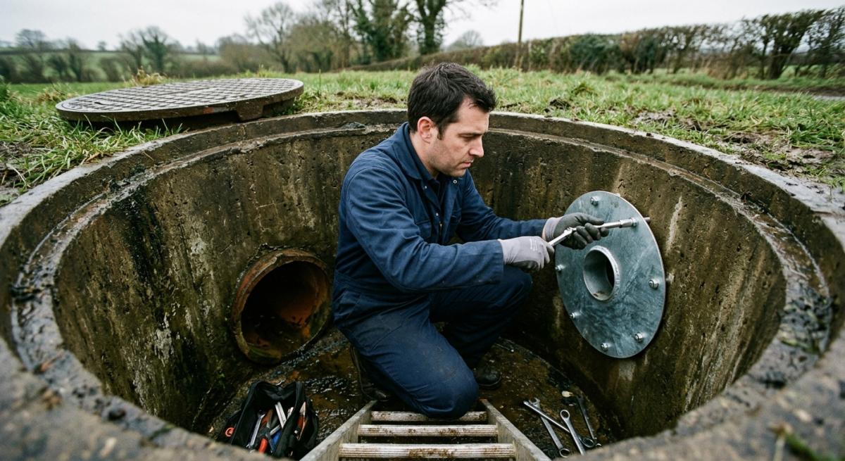
When mounting the plate within a concrete manhole or hydro-brake chamber, engineers must align the aperture precisely with the outlet pipe centre line. Positioning errors of just a few millimetres drastically alter calculated flow rates, causing either premature attenuation tank surcharging or excessive downstream discharge. To achieve a long-term watertight seal, fix stainless-steel plates using chemically anchored studs and neoprene gaskets.
Catalogue Engineering recommends following a strict 3-step alignment routine during installation:
- Clear all debris from the chamber wall and verify invert levels against the approved drainage design drawings using a laser level.
- Apply a continuous band of high-grade sealant around the outlet aperture before offering up the plate.
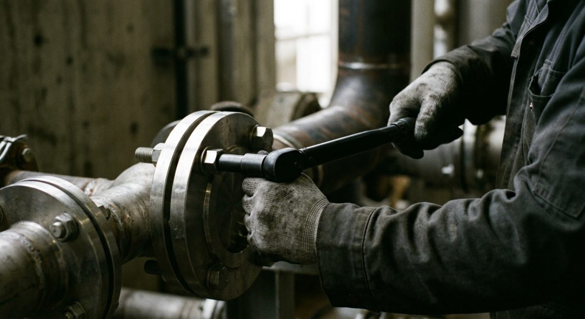
- Torque the stainless-steel fixings evenly in a cross pattern to prevent plate distortion and eliminate bypass leaks.
Managing Pipe Connections and Surrounding Sub-base Stability
Flawless pipe connections are essential to prevent groundwater ingress from compromising the structural backfilling around your attenuation facility. Failing to properly support surrounding soils causes pipe deflection, sheared joints, and costly site remediation.
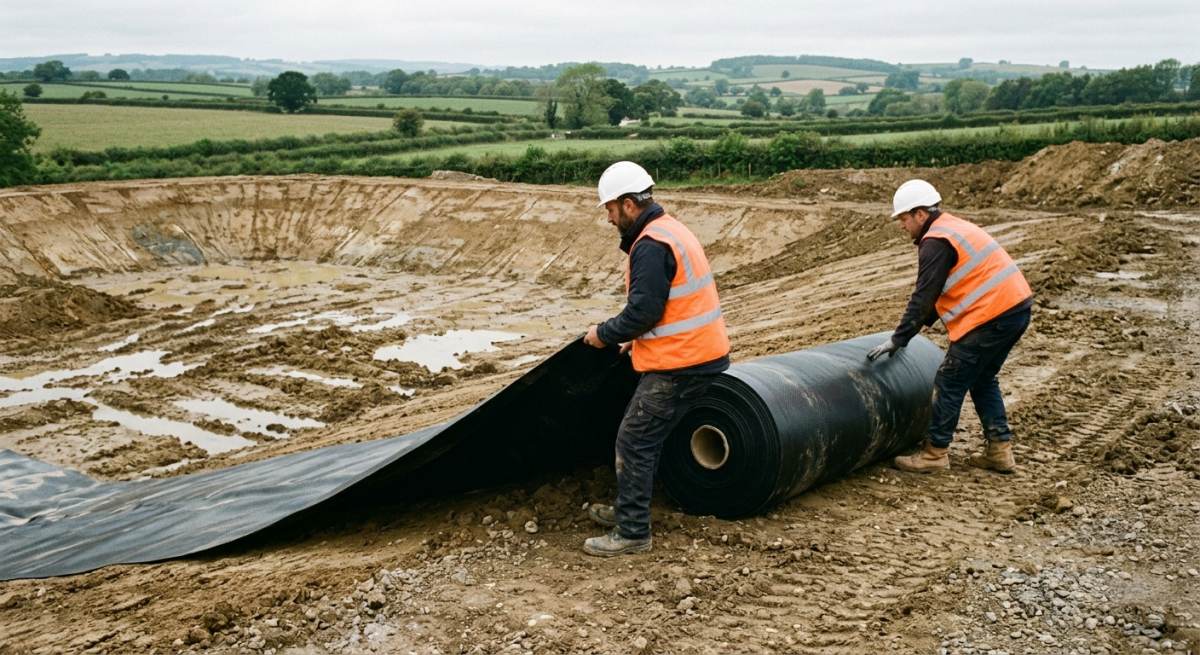
Connecting smooth-walled drainage runs to ribbed attenuation tanks requires specialised adapter couplings designed to handle differential settlement. Installers must lay a 150 mm well-graded granular bed beneath all incoming and outgoing pipework to provide uniform support. Once pipework is secured, engineers must carefully execute structural backfilling using compacted, rounded gravel in 150 mm layers. This approach protects adjacent geomembrane lining materials from sharp punctures while maintaining optimal load distribution across the sub-base.
Integrating Protective Screens and Access Points
Installing an integrated debris screen upstream of the orifice plate stops leaf litter and silt from blinding the aperture. Without adequate protection, small orifices rapidly block during heavy rainfall events and trigger unwanted system bypasses.
A well-designed installation features a removable stainless-steel mesh screen placed at an angle within the inspection chamber. This layout allows silt to drop into a dedicated sump below the pipe invert rather than settling against the orifice plate. Designing access covers directly above the screen and plate ensures maintenance crews carry out routine jetting and clearance work safely from ground level.
Follow this maintenance checklist to keep flow control chambers operating at peak efficiency:
- Inspect the upstream sump and clear accumulated silt every 6 months using a vacuum tanker.
- Lift and hose down the debris screen prior to the winter storm season.
- Check the geomembrane lining seals around chamber wall penetrations for signs of wear or water bypass.
Frequently Asked Questions around Attenuation Tank
What Is An Attenuation Tank And How Does It Work?
An attenuation tank is an underground storage system designed to hold excess rainwater during heavy storms. It temporarily stores the run off water from roofs, driveways, and car parks, releasing it slowly into the local drainage network at a controlled rate to prevent downstream flooding.
Why Do You Need An Orifice Plate In An Attenuation Tank System?
An orifice plate acts as the control valve that regulates how quickly water leaves the storage tank. By fitting a steel plate with a specifically sized hole at the outlet pipe, you restrict the water flow so that it never exceeds the maximum discharge rate permitted by local water authorities.
Can An Attenuation Tank Be Installed Under A Car Park?
Yes, attenuation tanks can certainly be installed beneath car parks and driveways, provided you choose a modular geocellular system or concrete tank designed for heavy traffic loads. These heavy-duty structures are engineered to withstand the weight of moving vehicles while storing thousands of litres of water underneath the surface.
How Often Should You Inspect And Clean An Attenuation Tank?
You should inspect your attenuation tank at least twice a year, usually in autumn and spring, to ensure it stays free from silt and debris. Regular maintenance involves checking the inlet and outlet pipework, clearing any sediment traps, and making sure the orifice plate is not blocked by fallen leaves or rubbish.
What Is The Typical Lifespan Of A Plastic Geocellular Attenuation Tank?
A high-quality geocellular attenuation tank will typically last for over 50 years when installed correctly according to manufacturer guidelines. The plastic crates are manufactured from durable recycled polypropylene, which does not rot or degrade easily when buried underground.
How Do You Prevent The Orifice Plate From Getting Blocked?
Installing a silt trap or catchpit upstream of the attenuation tank is the best way to prevent your orifice plate from clogging. These chamber units catch leaves, grit, and larger debris before the water reaches the tank, ensuring only clean water flows towards the small opening in the restriction plate.
How Do You Calculate The Required Size Of An Attenuation Tank?
You calculate the correct tank volume by assessing the total catchment area of your site, local rainfall data, and the maximum allowed discharge rate set by the local council. A drainage engineer usually performs complex hydraulic calculations to ensure the tank can handle a 1 in 100-year storm event, plus an extra allowance for climate change.
What Is The Average Cost Of Installing An Attenuation Tank?
The total cost of installing an attenuation tank system generally ranges from £150 to £350 per cubic metre of storage capacity, depending on site conditions and ground type. This estimate includes the cost of the structural crates or concrete tank, geotextile membranes, pipework, orifice plate, and the ground excavation work.
Do You Need Planning Permission To Install An Attenuation Tank?
You usually need planning approval for attenuation tanks as part of the wider sustainable drainage strategy for new developments or major refurbishment projects. Local planning authorities almost always require a detailed surface water management plan before granting full approval for construction work to begin.
What Happens To An Attenuation Tank During An Extreme Storm Event?
During an extreme storm, the attenuation tank simply fills up closer to its maximum capacity while the orifice plate continues to release water at the set safety limit. If rainfall exceeds the calculated design capacity of the system, a built-in emergency overflow pipe safely directs the excess water towards an approved secondary discharge point.
Ready to Discuss Your Attenuation Tank Project?
Get in touch with our specialists today for detailed site guidance, technical specifications, and a quotation tailored to your requirements.