Modern UK developments face strict environmental rules to manage surface water runoff before it enters local sewer networks. As heavy rainfall events increase across every city and town, engineers must design reliable underground drainage systems that hold back peak flows. Underground Stormwater Attenuation provides temporary storage below ground, collecting excess rainfall during major storms and releasing it slowly at an agreed rate. Central to this process is the underground Attenuation Tank, which acts as a subterranean reservoir beneath carparks, housing estates, or commercial sites. Storing water alone presents major technical challenges, as unmanaged discharge can quickly overwhelm downstream infrastructure and trigger severe localised flooding. By pairing structural storage with precise flow control devices, developers can satisfy UK SuDS Guidelines, protect surrounding property, and secure fast planning approvals. This comprehensive section examines why integrating accurate flow controls into subterranean storage units is indispensable for modern, flood-resilient civil engineering projects across the UK.
Property developers, civil engineers, and site managers face increasingly strict greenfield runoff limits set by Lead Local Flood Authorities across the UK. Designing an efficient surface water management system within a densely built-up area often leads to severe spatial constraints and conflicting technical requirements on site.
Failing to control peak discharge rates often leads to planning refusals or costly site redesigns under the strict performance criteria of the CIRIA C753 SuDS Manual. Without accurate hydraulic flow regulation, unmanaged surcharging can quickly flood adjacent local streets and cause structural ground damage exceeding £100000 across 1 site.
Installing advanced vortex flow control valves alongside a modular Attenuation Tank ensures collected water releases at a precise, pre-calculated litres-per-second rate. This integrated technical approach delivers dependable Stormwater Attenuation, ensuring full compliance with official SuDS Guidelines while minimising total excavation volumes and material costs on site.
KEY TAKEAWAYS
- Stormwater Attenuation systems collect excess rainfall during peak storm events and release it safely into local drainage networks at a controlled rate.
- Pairing a durable underground Attenuation Tank with dynamic flow control devices reduces required storage volumes by up to 30%, cutting overall installation costs.
- Adhering to national SuDS Guidelines protects local towns from surface water flooding while preventing costly planning delays for 100% of commercial and residential developments.
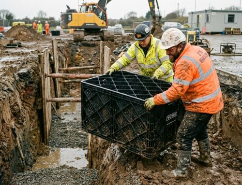
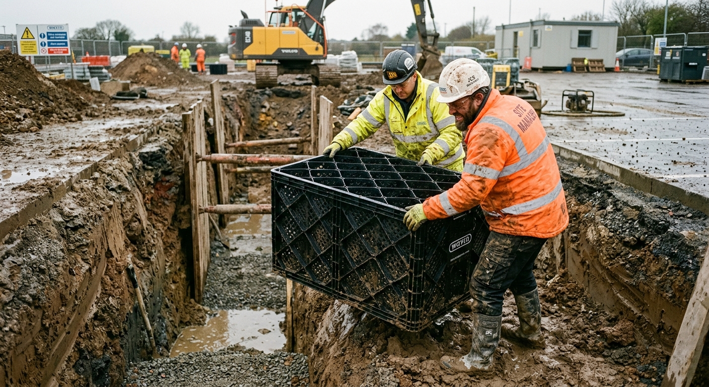
Engineers review the installation of underground attenuation crates on a modern UK commercial development.
Table of Contents
- The Role of Flow Control Devices in Managing Peak Runoff Rates
- Hydraulic Performance and Flood Prevention Principles
- Specialist Installation Practices and Site Integration
- Long Term Maintenance and CIRIA Compliance Requirements
- Frequently Asked Questions around Attenuation Systems
Need Specialist Advice on attenuation systems?
Speak to our technical team today for tailored specifications, regulations compliance, and practical support.
The Role of Flow Control Devices in Managing Peak Runoff Rates
Regulating Discharge to Prevent Downstream Flooding
Flow control devices restrict excess surface water by releasing stormwater into public sewers at a pre-determined greenfield rate. This controlled discharge protects local streets and watercourses from hydraulic overload during severe rainstorms.
When intense rainfall hits impermeable surfaces across a built-up area, the Peak Runoff Rate surges rapidly. Without intervention, this sudden influx overwhelms legacy drainage infrastructure built 50 to 100 years ago. Underground attenuation tanks store this volume, while the flow control mechanism acts as a precise throttle. By limiting outflow to 2 or 3 litres per second per hectare, the local network operates safely within its design limits. Local planning authorities in every town and city routinely mandate these hydraulic calculations to approve new developments.
Comparing Hydraulic Efficiency Across Device Types
Engineers generally select either a Vortex Flow Control or a traditional Orifice Plate to manage hydraulic head within an attenuation system. A Vortex Flow Control offers a wider clear opening at lower hydraulic heads, reducing the total storage volume required upstream by up to 30%.
An Orifice Plate relies on a simple fixed aperture, which means discharge rates vary significantly as water depth rises and falls inside the tank. In contrast, a Vortex Flow Control uses the fluid dynamic energy of the water to form a swirling air core. This air core throttles the flow without narrowing the physical opening, allowing the unit to maintain the permitted Peak Runoff Rate across varying hydraulic pressures. Because the physical opening remains up to 6 times larger than that of an Orifice Plate, the risk of structural blockage drops markedly.
Meeting Regulatory Compliance and Local Planning Standards
Lead Local Flood Authorities require surface water management plans that account for a 1-in-100-year storm event plus a 40% allowance for climate change. Installing precision-engineered flow units ensures developers satisfy water company adoptable standards under statutory guidelines.
Calculations must account for maximum design head, pipe gradient, and local catchments to avoid over-designing underground storage crating. Properly calibrated flow regulators ensure that discharged water never exceeds pre-development levels, securing final sign-off from local authorities. Stainless steel units manufactured from grade 304 or 316 material provide a 60-year lifespan, ensuring long-term compliance without structural degradation.
Protocol for Routine Maintenance and Inspection
Maintenance teams must follow a structured inspection routine to keep flow control units operating at maximum hydraulic capacity. Regular checks prevent debris buildup from altering design discharge rates across a 60-year lifespan.
- Clear sediment and silt accumulation from the concrete chamber sump using a vacuum tanker 2 times every 12 months.
- Inspect the stainless steel bypass door and pull-cord mechanism to verify smooth manual operation during high-water surcharges.
- Check the internal intake aperture for plastic pollution or organic debris and flush clean using high-pressure water jets.
| Specification | Primary Features | Lifespan | Cost Bracket | Building Regulations Compliance |
|---|---|---|---|---|
| Stainless Steel Vortex Flow Control (AISI 316) | Self-activating hydrodynamic design, non-blocking hydraulic aperture, no moving parts, optimized head vs discharge relationship | 100+ years | ££ | Building Regs Part H, CIRIA C753 SuDS Manual, DCG compliant |
| Precision Cut Orifice Plate (AISI 316) | Static flow restriction, calibrated circular opening, manual emergency bypass door option, low maintenance | 50+ years | £ | Building Regs Part H, BS EN 752 compliant |
| Manual Penstock & Integrated Check Valve (HDPE / 316 SS) | Adjustable aperture size, manual isolation spindle, backflow prevention mechanism, wall mounted design | 30+ years | ££ | Building Regs Part H, BS EN 13564, DCG compliant |
| Automated Telemetry Actuated Control Valve | Dynamic real-time discharge regulation, integrated water level sensors, solar or mains powered, remote override capability | 20+ years | ££££ | Building Regs Part H, CIRIA C753 SuDS Manual compliant |
Hydraulic Performance and Flood Prevention Principles
Managing Hydraulic Head to Stabilise Flow
Hydraulic Head dictates the pressure driving water through an attenuation system during heavy rainfall. Managing this variable pressure ensures that water releases into downstream networks at a safe, predictable velocity.
When intense storms hit a built-up area, water levels inside underground storage crates rise rapidly. This depth creates hydrostatic pressure that naturally forces water out at excessive speeds. Modern flow control devices harness this water depth, using fluid dynamic energy to generate a rotating vortex. This rotational motion creates a central air core that throttles outflow without requiring electrical power or moving components. Consequently, even as water depth fluctuates between 0.5 metres and 3 metres, the discharge remains strictly within pre-calculated safety thresholds.
Regulating Discharge Rate Across Peak Storm Events
Controlling the Discharge Rate prevents surcharging in municipal sewers by throttling high-volume run-off. This controlled release buffers local drainage infrastructure against sudden surges caused by 1-in-100-year storm occurrences.
Traditional orifice plates feature a simple linear flow response, meaning they drain too slowly at low water depths and allow excessive flow when water levels peak. Advanced vortex valves deliver an optimised hydraulic curve that achieves its maximum design flow much earlier in the storm cycle and maintains it consistently. Maintenance teams must carry out a simple 3-step routine to maintain optimum performance
- Clear sediment buildup around the intake chamber 2 times every 12 months.
- Inspect the internal air core pathway for trapped debris or structural blockages.
- Verify manual bypass pull-cord operation to ensure emergency drain-down functionality.
This predictable flow curve maximises the storage capacity of the underground attenuation tank while ensuring downstream sewer connections never exceed their maximum volumetric capacity.
Integrating Flow Control for Long Term Flood Prevention
Effective Flood Prevention relies on matching site run-off speeds to the greenfield discharge rates required by local planning authorities. Installing precision flow regulators guarantees compliance with these environmental standards while protecting surrounding local streets.
Without tailored flow restrictions, attenuation crates merely delay water movement rather than managing it safely. High-density residential developments and commercial centres produce massive volumes of surface run-off due to impermeable concrete surfaces. Connecting a calibrated flow control chamber to the attenuation outlet forces excess water to back up safely into the engineered storage crates. This integrated approach ensures that stormwater leaves the site at a rate local rivers and drainage channels can easily handle, delivering reliable performance across a standard 60-year asset lifespan.
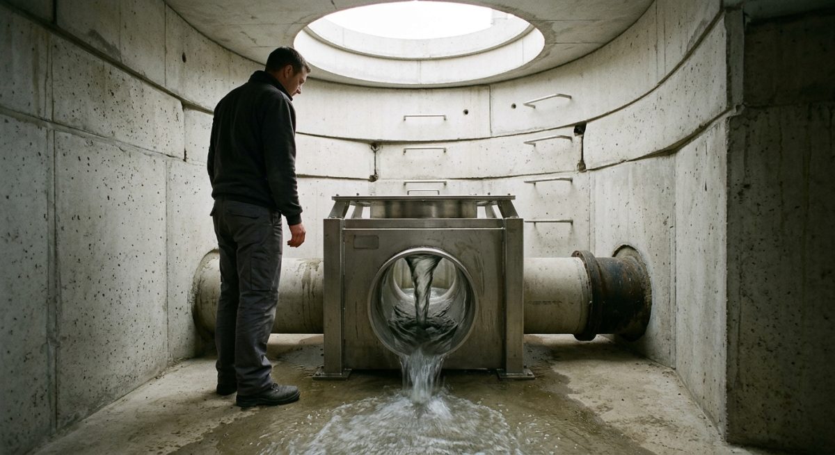
A vortex flow control unit mounted inside an attenuation chamber regulates stormwater discharge rates.
Specialist Installation Practices and Site Integration
Positioning Flow Controls and Silt Trap Integration
Correct positioning of a flow control unit relies on placing it downstream of efficient settlement chambers to prevent debris blockage. Pre-cast concrete manholes or modular attenuation tanks must incorporate these units at precise invert levels to maintain designed hydraulic heads.
Ground engineers must ensure that Silt Trap Integration occurs upstream of the flow control device. Sediment and heavy grit collect in dedicated catchpits fitted with 300 mm sumps, preventing particulate build-up from altering the orifice dimensions or choking vortex chambers. In dense built-up areas, installing these traps protects downstream drainage networks from premature silting. Proper site layout provides 100% access for suction tankers during routine maintenance, safeguarding long-term hydraulic performance across a 60-year design life. In addition, manhole access covers must be rated to 40 tonnes to withstand heavy traffic loads above local streets while keeping inspection points clear.
Penetration Integrity with Geomembrane Liners
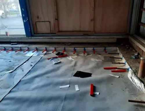
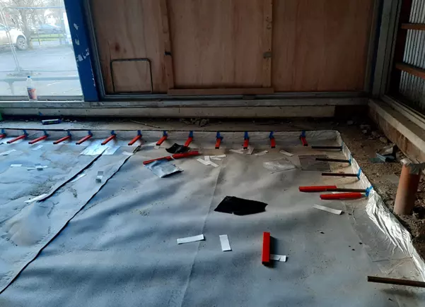
Impermeable attenuation crates require watertight structural seals wherever pipework penetrates the outer protective wrapping. Installing flow control units alongside Geomembrane Liners demands specialist top-hat adapters and double-welded joints to stop groundwater ingress or storm runoff leakage.
When contractors install below-ground attenuation tanks in contaminated ground or high-water-table areas, membrane integrity is essential. Geomembrane Liners isolate the stored storm volume, while compatible Gas Barrier Systems stop hazardous ground gases like methane or radon from entering the drainage structure. Pipe penetrations housing flow control sumps must be fully sealed using factory-fabricated puddle flanges and continuous perimeter welds. A heavy-duty non-woven geotextile fleece weighing 300 g/m2 should cushion the membrane to protect it against sharp stones during backfilling. Field technicians perform 100% non-destructive air-pressure testing on every seam to confirm compliance before backfilling with 10 mm to 20 mm clean aggregate.
Pre-Handover Testing and Inspection Steps
Commissioning flow control hardware requires systematic validation of invert levels, orifice diameters, and emergency bypass operation before adoption by local water authorities. Thorough testing guarantees that discharge rates strictly match the calculated greenfield runoff figures for the development.
Site engineers follow a standard 3-step sign-off process to confirm system readiness.
- Verify that internal orifice dimensions match the approved hydraulic calculations using calibrated callipers accurate to within 1 mm.
- Inspect all upstream catchment areas to ensure 100% clearance of construction debris, silt, and temporary pipe plugs.
- Flood the local chamber with water to verify that vortex action initiates correctly and that the emergency overflow operates smoothly at maximum hydraulic head.
Failing to execute this checklist leads to unexpected site flooding, costly retrofits, and potential council fines exceeding £5000 per incident. Contractors must submit completed commissioning certificates to local water authorities to satisfy section 104 adoption agreements across England and Wales.
Long Term Maintenance and CIRIA Compliance Requirements
Adhering to the CIRIA C753 SuDS Manual Framework
Compliance with the CIRIA C753 SuDS Manual ensures that underground attenuation systems meet strict British standards for hydraulic performance and durability. Adopting these national guidelines protects local adoption agreements with water companies under Section 104 frameworks.
Designers must specify flow control devices that match exact discharge limits over a 60 to 100-year design life. Standard vortex flow controls and engineered orifice plates help manage peak storm events in busy built-up areas, keeping run-off within greenfield rates. Aligning device specifications with CIRIA C753 rules guarantees that site drainage assets remain functional, sustainable, and easy for local authorities to approve.
Implementing Effective Silt Management and Inspection Routines
Robust Silt Management prevents heavy sediment from clogging flow control apertures and reducing attenuation tank storage. Routine maintenance clears accumulated debris before it threatens the hydraulic capacity of the local drainage network.
Fine soils, leaves, and road grit washed from town surfaces gradually collect inside catchment chambers. Without scheduled removal, this material travels downstream and restricts low-flow outlets. Site managers should execute a 3-step inspection sequence every 6 months to ensure optimal performance.
- Inspect the upstream silt trap and sump chamber to check if sediment depth exceeds 200 mm.
- Vacuum out collected grit using a standard suction tanker to restore total storage volume.
- Flush the flow control unit with clean water to remove residual detritus from internal faces.
Integrating a Maintenance Bypass for Network Continuity
A dedicated Maintenance Bypass allows operational teams to isolate or clean a flow control device without causing surface flooding. This integrated feature maintains uninterrupted drainage while engineers carry out emergency jetting or routine inspection work.
When unexpected blockages occur, water levels inside the inspection chamber rise rapidly. Installing a manual drawdown door, penstock valve, or high-level bypass pipe creates an immediate relief route. Incorporating a Maintenance Bypass into early chamber designs reduces site flood risk, cuts emergency clearance bills by up to 50%, and safeguards surrounding property during severe 1-in-100-year rainfall events.
Precise measurement of flow control components ensures exact discharge rates during peak rainfall events.

Frequently Asked Questions around Attenuation Systems
What Is An Underground Stormwater Attenuation System?
An underground stormwater attenuation system is a buried storage structure designed to collect excess rainwater and hold it temporarily during heavy downpours.
It then releases the water slowly into the local drainage network or rivers. This prevents local flooding in towns, cities, and streets by managing peak rainfall volumes safely.
How Does A Flow Control Device Work Within An Attenuation System?
A flow control device works by restricting the rate at which stored rainwater exits the attenuation tank into the main sewer network.
As water levels rise inside the tank, the device creates a vortex or uses a fixed orifice to limit outflow to a set limit, such as 5 litres per second. This ensures downstream pipes do not become overwhelmed during extreme weather events.
Why Are Flow Control Devices Mandatory For Drainage Approvals?
Flow control devices are mandatory because planning authorities require new developments to match natural greenfield runoff rates to prevent downstream flood risk.
Lead Local Flood Authorities and water companies will not approve site plans unless a verified flow control mechanism is installed. Without these devices, unmanaged stormwater would surge into public sewers, causing widespread sewer surcharging and property damage.
What Is The Typical Lifespan Of An Underground Attenuation Tank?
A quality underground attenuation tank has a design lifespan of 50 to 100 years when installed and maintained correctly.
Modern crate systems and concrete tanks are built from highly durable plastics or structural concrete that resist soil pressure and heavy vehicle loads. Regular maintenance over 1 to 2 year intervals ensures the system reaches its full operational lifespan without structural failure.
How Often Should An Attenuation System Be Inspected And Maintained?
You should inspect an attenuation system at least 2 times a year, typically in spring and autumn, and after major storm events.
Maintenance involves checking catchpits for silt buildup, inspecting the flow control unit for blockages, and flushing out debris. Regular maintenance prevents silt from reducing storage capacity by up to 20% over 5 years.
What Happens If An Attenuation Tank Does Not Have A Flow Control Device?
Without a flow control device, stormwater flows straight through the underground tank without any restriction, rendering the storage capacity ineffective.
The tank simply fills and empties instantly at full speed during torrential rain. This leads to severe surface water flooding on surrounding streets and causes backup problems further down the municipal drainage pipe network.
What Types Of Flow Control Devices Are Most Common In The UK?
The 2 most common types of flow control devices used in the UK are hydro-brake vortex controls and fixed orifice plates.
Hydro-brake vortex controls are preferred because they have larger clearance openings than standard orifice plates, reducing the risk of blockages by up to 50%. Orifice plates are simpler and lower cost, making them suitable for smaller domestic or light commercial projects.
Can Flow Control Devices Be Retrofitted To Existing Underground Systems?
Yes, engineers can retrofit flow control devices to existing chamber walls or pipe outlets within established drainage networks.
A technical specialist must measure the existing chamber dimensions and calculate the required flow rate before installation. Retrofitting helps site owners update old infrastructure to meet current 1 in 100 year flood standards without replacing the entire underground tank.
How Much Storage Volume Does A Commercial Site Require?
Storage volume varies based on site area, local rainfall data, and permitted discharge rates, but typical sites require between 100 cubic metres and 1000 cubic metres of attenuation space.
Structural engineers calculate this capacity based on extreme storm models, including a 40% allowance for climate change. Factors like soil permeability and hard surface coverage directly impact the final storage size needed.
How Do Attenuation Systems Support Sustainable Drainage Systems Principles?
Attenuation systems support Sustainable Drainage Systems principles by mimicking natural water catchments and controlling flood risk at the source.
By pairing storage tanks with silt traps, oil separators, and flow controls, these systems capture pollutants while holding water back. This improves water quality in local rivers and protects communities from unexpected flash flooding.
Ready to Discuss Your attenuation systems Project?
Get in touch with our specialists today for detailed site guidance, technical specifications, and a quotation tailored to your requirements.