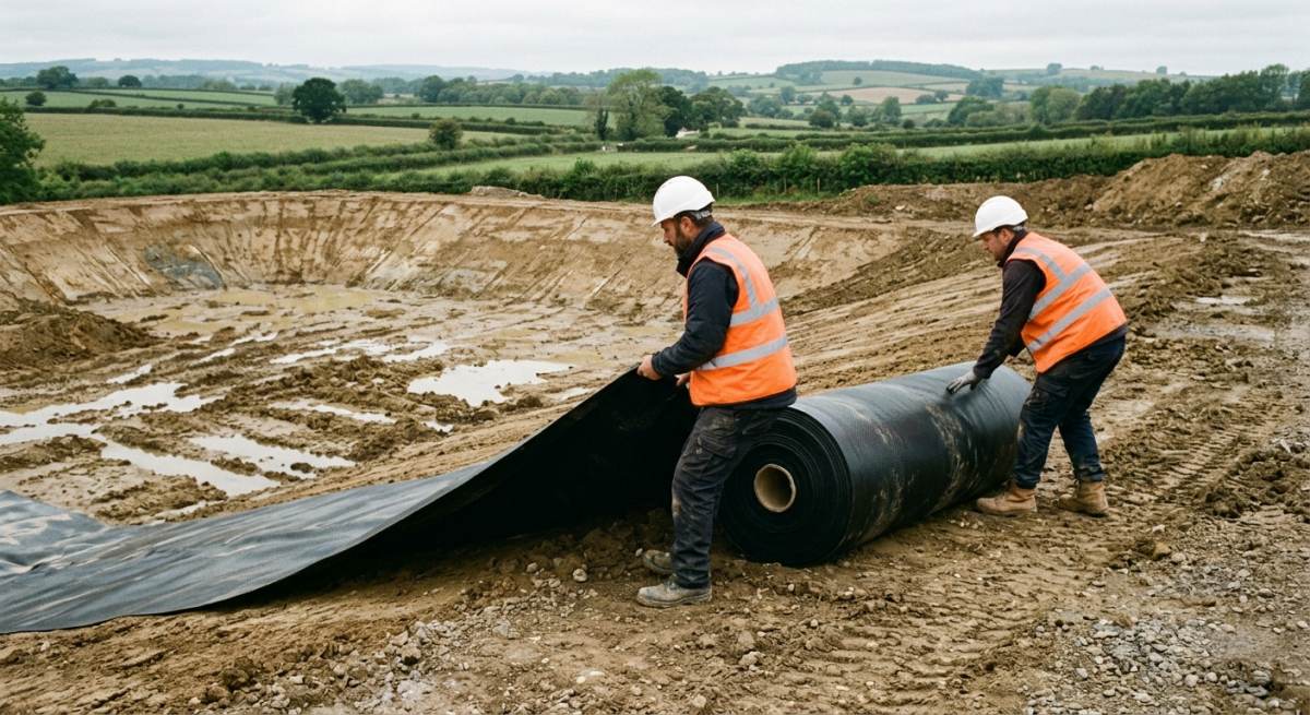
Developing a modern Brownfield Site presents distinct ground-engineering challenges, particularly when integrating effective Stormwater Attenuation schemes across former industrial land. Historical site use frequently leaves heavy metals, toxic hydrocarbons, and hazardous chemical residues trapped within the shallow ground matrix. When unmanaged rainwater infiltrates these compromised ground layers without adequate containment, it risks mobilising legacy pollutants into local watercourses, town drainage networks, or deeper aquifers.
Ground-engineering professionals and site developers must navigate strict Contaminated Land Management frameworks alongside national technical guidance like CIRIA C753 to ensure statutory compliance. This comprehensive article outlines the core physical risks, structural load considerations, and regulatory obligations involved in installing modular sub-surface storage systems on compromised ground. By exploring geo-textile barriers, impermeable membrane liners, and specialised site-specific drainage strategies, readers will gain practical insights into mitigating long-term environmental liability while delivering robust water management infrastructure across complex redevelopment projects in built-up areas.
Installing sub-surface drainage systems on heavily polluted redevelopment land creates severe technical friction and regulatory headaches for site managers and commercial developers. Unchecked groundwater movement through unsealed contaminated soil layers threatens to wash legacy industrial toxins directly into surrounding water networks and municipal drainage channels.
Failing to contain these sub-surface toxins can trigger severe regulatory penalties, costly construction halts, and outright planning refusals from local authorities. In fact, non-compliance with the CIRIA C753 SuDS Manual can increase total site remediation costs by up to 35% while delaying project completion timelines by over 6 months.
Deploying high-specification impermeable geomembrane wraps alongside sealed attenuation crates prevents hazardous leachates from escaping into nearby ground layers. These site-specific engineering methods allow developers to satisfy strict environmental protection rules cleanly while keeping long-term site remediation budgets firmly on track.
KEY TAKEAWAYS
- Infiltrating untreated surface water through polluted soil risks dragging legacy industrial contaminants directly into local groundwater supplies, making fully wrapped, impermeable attenuation tanks essential for site safety across every modern Brownfield Site project.
- Adhering to recognised standards such as CIRIA C753 ensures that engineered Stormwater Attenuation installations meet strict UK environmental guidelines while mitigating long-term civil liability for property developers and civil engineering contractors.
- Specifying heavy-duty geomembranes alongside load-tested sub-surface crates delivers an operational design life exceeding 60 years without risking premature chemical degradation from aggressive ground-based hydrocarbons or toxic soil contaminants.
Table of Contents
- Selecting Geomembranes and Gas Barrier Liners for Attenuation Crates
- Preventing Pollutant Ingress and Contaminant Migration
- Structural Foundation and Backfill Procedures on Poor Ground
- Validation Integrity Testing and Long Term Maintenance Requirements
- Frequently Asked Questions around Attenuation Systems
Need Specialist Advice on attenuation systems?
Speak to our technical team today for tailored specifications, regulations compliance, and practical support.
Selecting Geomembranes and Gas Barrier Liners for Attenuation Crates
Material Selection for Sub-surface Contaminant Protection
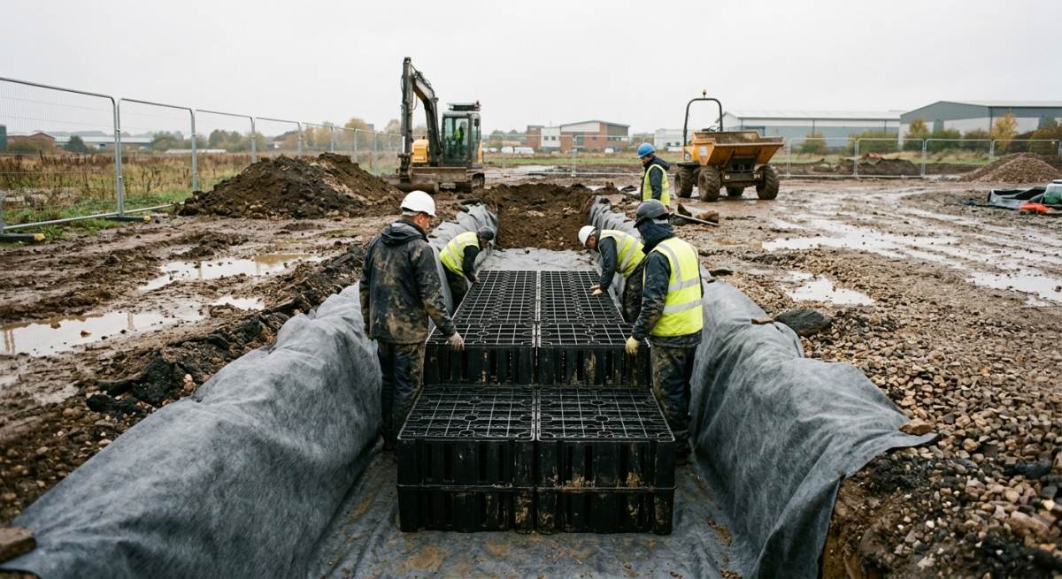
Specifying the correct Geomembrane Liners prevents hazardous ground-gas and volatile organic compounds from entering modular Attenuation Crates placed in contaminated ground. Engineers must evaluate site-specific soil chemistry to ensure full chemical compatibility with heavy metals and organic pollutants over a 60-year design life.
Traditional polypropylene membranes often degrade rapidly when exposed to aggressive volatile hydrocarbons, phenols, or ground solvents in historical industrial areas. High-density polyethylene solutions, such as a 1 mm-thick HDPE Membrane, provide superior chemical resistance and long-term structural durability beneath heavy traffic loads in busy towns.
Heavy-duty non-woven geotextile protection layers, rated at 300 g per square metre, must be installed both above and below the liner. This protective sandwich shields the barrier against sharp puncture damage caused by coarse recycled aggregates during initial compaction and backfilling operations.
Hydrocarbon Barrier Integration with Modular Stormwater Cells
Integrating a specialised Hydrocarbon Barrier around sub-surface storage tanks creates a completely sealed impermeable barrier that resists lateral groundwater ingress. This dual-purpose barrier system simultaneously blocks dangerous methane gas migration while retaining stored surface water for controlled discharge into local drainage networks.
When former industrial brownfield sites contain residual oils, tar residues, or diesel contamination, standard geomembranes fail to prevent vapour permeability. Multi-layer aluminium foil laminate membranes provide an effective zero-permeability shield against volatile organic compounds across complex sub-surface geometries.
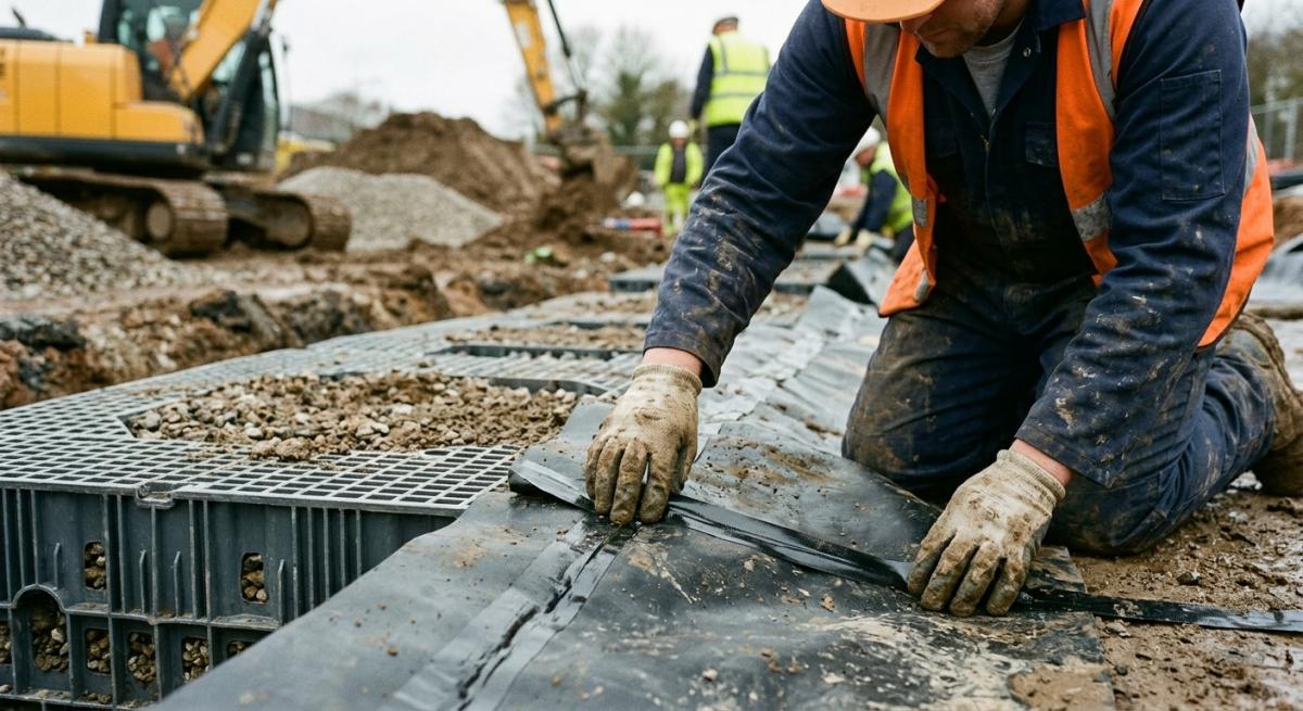
Contractors must execute precise perimeter detailing around pipe penetrations, using pre-formed top-hat seals and heavy-duty butyl tape, to maintain complete structural integrity across 100% of the tank boundary. This prevents toxic leachate from mixing with clean surface water run-off stored within the sub-surface void spaces.
Quality Assurance and Joint Testing Protocols
Rigorous site testing protocols verify that all membrane welds maintain complete air-tight and water-tight seals throughout the installation cycle. Onsite quality assurance routines identify microscopic pinholes before structural backfilling covers the completed tank assembly.
To ensure long-term structural performance on high-risk sites, specialist installation crews must follow a strict 3-step membrane verification procedure.
- Perform continuous visual inspection of all double-wedge welded seams across the entire 100% surface area to spot unbonded overlaps
- Conduct non-destructive spark testing at 20 kV along all hand-welded extrusion penetration details and tricky corner joins
- Complete a pressurised air-channel test at 2 bar for 5 minutes on double-seam tracks to confirm zero pressure drop
| Specification | Primary Features | Lifespan | Cost Bracket | Building Regulations Compliance |
|---|---|---|---|---|
| High-Load Polypropylene Geocellular Crates | Wrapped in 1.0mm HDPE welded membrane, 700 kN/m² compressive strength, modular zero-infiltration design | 50 years | ££ | Part H3, CIRIA C753 SuDS Manual, BS EN 17152-1 |
| Precast Concrete Box Culverts | Heavy-duty structural capacity, elastomeric hydrophilic joint seals, high resistance to aggressive soil contaminants | 100 years | ££££ | Part H3, BS EN 14844, CIRIA C753, DCG Standards |
| Twin-Wall Smoothbore HDPE Pipe Systems | Electrofusion welded impermeable joints, SN8 ring stiffness, flexible design resistant to hydrocarbon exposure | 60 years | £££ | Part H3, BS EN 13476, CIRIA C753, Sewers for Adoption |
| Cast-in-Situ Reinforced Concrete Tanks | Monolithic structural build, internal chemical-resistant elastomeric coating, integral waterstops for total containment | 100 years | £££££ | Part H3, BS EN 1992-3 Eurocode 2, BS 8582 |
Preventing Pollutant Ingress and Contaminant Migration
Impermeable Geomembrane Encapsulation
Isolating modular geocellular crates within a fully Sealed Attenuation Tank prevents toxic ground contaminants from entering clean storm-water networks. This fully tanked approach creates an impenetrable barrier that aligns with best-practice guidance set out in the SuDS Manual for high-risk brownfield development.
Without robust encapsulation, sub-surface water movements pull heavy metals, cyanides, and organic solvents into storage crates during seasonal groundwater rises. Conversely, exfiltration from an unlined crate system pushes stored rainwater out into surrounding contaminated ground, washing mobile toxins down into vulnerable aquifer systems. Specifying a fully sealed, heavy-duty geomembrane jacket protects local groundwater while ensuring a stable 60-year service life beneath busy town centres and commercial developments.
Proper detailing around pipe penetrations remains a key priority during initial installation. Structural engineers must specify bespoke puddle flanges and prefabricated top-hat boots, which are welded directly to the main membrane layer. This meticulous level of detailing prevents diffuse pollution from entering at the weakest interface points of the storm-water storage structure.
Hydrocarbon Resistance and Barrier Selection
Selecting membrane materials with certified Hydrocarbon Resistance ensures lasting protection against volatile organic compounds and historical fuel residues. Standard polyolefin liners can swell and degrade when exposed to aggressive petrochemical contaminants, leading to premature lining failure and structural risk.
Engineers must review detailed site-investigation reports to match membrane polymer blends against specific soil contaminants present on former industrial sites. Co-extruded barrier membranes featuring flexible aluminium foil cores or specialised multi-layer polymers prevent vapour transmission alongside liquid ingress. These reinforced barrier systems maintain high puncture resistance and chemical stability across a 50-year design life, safeguarding storm-water runoff from legacy pollution.
In areas with high concentrations of polycyclic aromatic hydrocarbons or diesel fuel, standard 1 mm membrane thicknesses are often insufficient. Local authorities and environmental regulators frequently specify 1.5 mm to 2 mm thick reinforced chemical-barrier membranes to withstand localised structural shear stresses and aggressive ground conditions across 100% of the tank footprint.
Verifying System Integrity
Executing rigorous quality control procedures on all Welded Joints ensures the underground attenuation facility remains completely water-tight under heavy vehicle loadings. Site technicians must complete a 3-step quality assurance sequence before backfilling the excavated area.
- Conduct continuous visual inspections and high-voltage spark testing along 100% of heat-fused seams to detect microscopic pinholes.
- Perform low-pressure air tests on double-wedge welded channels for a minimum of 5 minutes to confirm gas-tight containment.
- Sign off formal quality documentation and place a 300 g heavy-duty protective geotextile layer over the membrane to guard against sharp backfill materials.
Field testing must be carried out by qualified technicians holding appropriate UK certification. Documenting every seam test creates a verifiable audit trail required by local planning authorities and water companies before final adoption. Additionally, keeping clean rainwater separated from surrounding soil lowers long-term liability for site owners and maintenance contractors.
Structural Foundation and Backfill Procedures on Poor Ground
Sub-grade Preparation and Geotextile Membrane Installation
Sub-grade preparation on contaminated brownfield ground requires complete removal of soft spots followed by the installation of a high-density geotextile separation layer. This procedure isolates sub-surface contaminants while establishing a stable foundation base for heavy attenuation modules.
On low-bearing soils commonly found across former industrial sites in built-up areas, site teams must rigorously inspect and test the formation level. Installing a continuous heavy-duty geotextile membrane prevents fine soil particles from migrating into the attenuation zone and destabilising the underlying ground structure. Site engineers must execute the installation using a clear 3-step preparation routine.
- Excavate the brownfield site to the specified target depth and trim the sub-grade level smoothly to clear sharp debris.
- Lay an impermeable geotextile liner or heavy-duty geomembrane with minimum 300 mm overlaps across all jointed seams.
- Spread a 150 mm thick bed of clean sand or granular material to protect the protective liner from puncture risks.
Aggregate Backfill and Compaction Standards
Correct placement of Aggregate Backfill around sub-surface storage units prevents horizontal movement and protects structural components from excessive earth pressure. Granular material must be laid in uniform layers to maintain consistent side support across the entire attenuation footprint.
Engineers should specify Type 1 crushed concrete or clean crushed gravel surrounding all geocellular tanks. Using loose fill, uncalibrated rubble, or cohesive clay reduces lateral support and drastically increases the likelihood of structural collapse under heavy operational conditions. Attenuation units require high Crushing Strength ratings to withstand both lateral pressure and deep ground surcharge.
System installer teams must apply granular backfill in maximum 150 mm layers, using light compaction equipment within 500 mm of the tank edge to avoid direct impact damage.
Structural Load Bearing and Traffic Loading Protection
Calculating the correct Structural Load Bearing capacity ensures attenuation tanks remain intact under maximum site demands. Proper load distribution methods protect subterranean tanks beneath local streets and busy delivery yards from ground movement.
When brownfield attenuation systems sit beneath active car parks or access roads, engineers must design cover depths capable of absorbing extreme Traffic Loading. High-density plastic crates or modular concrete units must meet minimum vertical load thresholds of 400 kN/m2 to guarantee long-term performance under daily lorry passes.
Incorporating reinforced concrete distribution slabs over the upper geotextile layer helps spread heavy point loads away from vulnerable crate edges. This engineered approach prevents differential settlement and guarantees a 60-year service life across challenging brownfield developments in any town or city.
Validation Integrity Testing and Long Term Maintenance Requirements
Verifying Geomembrane Performance Through Integrity Testing
Integrity Testing verifies that the impermeable geomembrane liner around sub-surface attenuation crates remains entirely leak-free following backfilling. This process prevents contaminated groundwater from entering the attenuation cell and stops harvested stormwater from leaching into surrounding brownfield soils.
Engineers must specify tracer gas detection or high-voltage electronic leak location methods before final sign-off. On compromised brownfield land, any micro-puncture in the heavy-duty geomembrane invalidates environmental risk models and breaches local authority planning conditions. Compliance with BS 8582 requires rigorous validation logs to prove the sub-surface structure completely isolates stored runoff from ground contaminants.
Double-welded seams must undergo vacuum box testing or dual-track pressure testing prior to backfilling operations. Soil sampling near perimeter monitoring wells provides ongoing validation during early operational phases, confirming that no leachate escapes into surrounding ground.
Implementing Pre-Treatment Silt Traps and Asset Care
Silt Traps installed upstream of the attenuation matrix capture heavy suspended solids and hydrocarbon residues before stormwater enters the primary storage unit. Removing these particulates protects internal channel voids from premature clogging and reduces long-term operational costs across built-up area developments.
Untreated sediment carrying heavy metals or polycyclic aromatic hydrocarbons can settle within the crate matrix, turning a clean storage asset into a hazardous waste liability. Asset managers must enforce a strict inspection regime to keep flow control chambers clear and preserve storage capacity over a 60-year service life. To maintain hydraulic efficiency, site teams must follow a structured 3-step maintenance procedure during every scheduled site visit.
- Inspect Silt Traps, catchpits, and oil separators every 3 months to clear trapped sediment, organic debris, and floating hydrocarbon films.
- Conduct an internal Maintenance Inspection using specialised CCTV camera crawlers every 12 months to verify crate structural integrity and identify localised silting patterns.
- High-pressure jet flush connected pipework and clean orifice plates at 24-month intervals to clear lingering obstructions and maintain design discharge rates.
Long-Term Asset Governance and Discharge Licences
Long-term maintenance plans establish clear legal responsibility for site drainage infrastructure throughout a 100-year operational lifecycle. Securing formal adoption by local water authorities guarantees that sub-surface attenuation assets undergo scheduled servicing, independent audits, and continuous environmental monitoring.
Failure to execute routine maintenance leads to severe silt accumulation, which reduces designed storage volume by up to 40% within 10 years. On brownfield sites, unmaintained units risk localised surcharge, forcing polluted surface water into local streets and nearby watercourses. Landowners must archive all validation certificates, Integrity Testing logs, and clearance records within the master site safety file. Proper documentation ensures full compliance with environmental licences, satisfies building control bodies, and protects downstream catchments across every town and city.
Frequently Asked Questions around Attenuation Systems
What Is A Stormwater Attenuation System On A Brownfield Site?
A stormwater attenuation system on a brownfield site is a subterranean storage structure designed to collect excess rainwater runoff and release it at a controlled rate into local drainage networks. Unlike traditional soakaways, these units temporarily hold large volumes of surface water during heavy rainfall events to prevent local flooding.
On brownfield ground, these systems are fully sealed using impermeable liners to stop clean stormwater from escaping into contaminated soil. They provide a safe, controlled way to manage surface water on compromised land where natural ground infiltration is impossible.
Why Are Infiltration Systems Unsuitable For Contaminated Brownfield Land?
Infiltration systems are unsuitable for contaminated brownfield land because soaking rainwater directly into polluted ground can dissolve contaminants and wash them into local groundwater supplies. This process, known as leaching, can spread heavy metals, hydrocarbons, and chemicals into nearby rivers and drinking water aquifers.
To prevent environmental harm, regulatory bodies such as the Environment Agency prohibit direct ground infiltration on contaminated sites. Designers must specify attenuation systems that store water in sealed chambers before discharging it safely into public sewers or watercourses.
How Do Impermeable Geomembranes Protect Attenuation Tanks From Pollution?
Impermeable geomembranes wrap around the attenuation tank to form a watertight barrier that prevents clean stormwater from escaping and keeps ground contaminants from entering the storage cell. These heavy-duty liners are typically made from 1 mm to 2 mm thick high-density polyethylene or polypropylene materials.
Site engineers weld the membrane joints using twin-wedge hot-air techniques to ensure continuous seal integrity. Heavy-duty geotextile fleece layers are installed on both sides of the geomembrane to shield it against punctures from sharp gravel or soil debris.
What Load-Bearing Capacity Is Required For Sub-Surface Attenuation Crates?
The required load-bearing capacity depends on the depth of the burial and the traffic loads above, typically ranging from 20 to 70 tonnes per square metre. Crates placed under pedestrian pathways or soft landscaping require lower ultimate compressive strengths of around 20 to 30 tonnes per square metre.
Crates installed beneath car parks, delivery lanes, or access routes for emergency vehicles demand heavy-duty units capable of supporting 40 to 70 tonnes per square metre. Engineers conduct detailed structural calculations to ensure the modular crates resist vertical vehicle weights and lateral earth pressures over their full operational life.
Which Regulations Govern Attenuation Installations On Brownfield Land In The UK?
Attenuation installations on brownfield land in the UK are governed by the Building Regulations Part H, the National Planning Policy Framework, and Environment Agency pollution prevention rules. Development proposals must also follow technical standards set out in CIRIA C753, widely known as The SuDS Manual.
Local Lead Local Flood Authorities review these plans to ensure discharge rates do not exceed greenfield runoff rates. Developers must present robust site-investigation reports and engineering drawings before gaining planning approval for drainage works on contaminated ground.
How Is Silt Managed Within A Sealed Brownfield Attenuation System?
Silt is managed by installing pre-treatment devices such as catchpits, silt traps, and vortex separators upstream of the primary attenuation tank. These units slow down incoming water, allowing heavy particles, grit, and debris to settle out before reaching the main storage crates.
Preventing silt accumulation inside a fully sealed tank is vital because internal cleaning is difficult once the site is complete. Site managers must inspect pre-treatment chambers 2 to 4 times per year and clear trapped sediment using suction tankers to maintain long-term storage capacity.
What Is The Typical Lifespan Of A Brownfield Attenuation Tank?
A modern, high-quality brownfield attenuation tank has a design lifespan of at least 50 to 60 years when installed correctly. Modular plastic crates made from virgin polypropylene offer exceptional resistance to chemical degradation caused by soil contaminants.
To achieve this maximum service life, maintenance teams must protect the upstream pre-treatment equipment and prevent silt build-up. Regular inspections ensure the internal storage volume remains clean and fully functional throughout the operational lifetime of the building development.
Can Brownfield Attenuation Systems Be Installed In High Groundwater Conditions?
Yes, brownfield attenuation systems can be installed in high groundwater conditions provided that flotation risk calculations are completed and anti-buoyancy measures are added. High water tables exert upward hydrostatic pressure that can lift hollow attenuation tanks out of the ground.
Engineers prevent tank flotation by pouring a heavy concrete anchor slab beneath the system or by using specialised strap-down anchoring systems. Increasing the depth of clean backfill material over the top of the tank also provides extra downward weight to hold the structure secure.
How Do Flow Control Devices Regulate Water Release From Attenuation Tanks?
Flow control devices limit the discharge rate of stormwater leaving the attenuation tank by using a calibrated hydro-brake or orifice plate installed in a downstream inspection chamber. These devices restrict water flow to a precise, pre-agreed rate measured in litres per second.
When heavy rain fills the attenuation tank, the flow control unit creates a vortex or hydraulic restriction that prevents downstream sewers from surcharging. Water accumulates safely inside the sealed attenuation crates and drains away slowly as rainfall subsides.
What Is The Cost Impact Of Installing Attenuation Tanks On Contaminated Sites?
Installing attenuation tanks on contaminated sites typically increases civil engineering costs by 15% to 30% compared to greenfield installations. Extra expenses stem from hazardous soil removal, specialist membrane welding, and additional site-investigation testing.
Contractors must also pay specialised muck-away fees to dispose of contaminated excavation spoil at licensed landfill facilities. Investing in robust pre-treatment systems and high-grade protective geotextiles adds initial capital cost but prevents expensive remediation work later in the project lifecycle.
Ready to Discuss Your attenuation systems Project?
Get in touch with our specialists today for detailed site guidance, technical specifications, and a quotation tailored to your requirements.