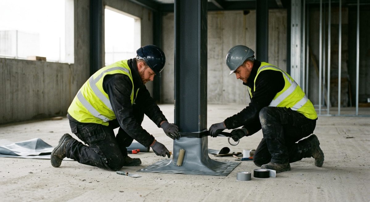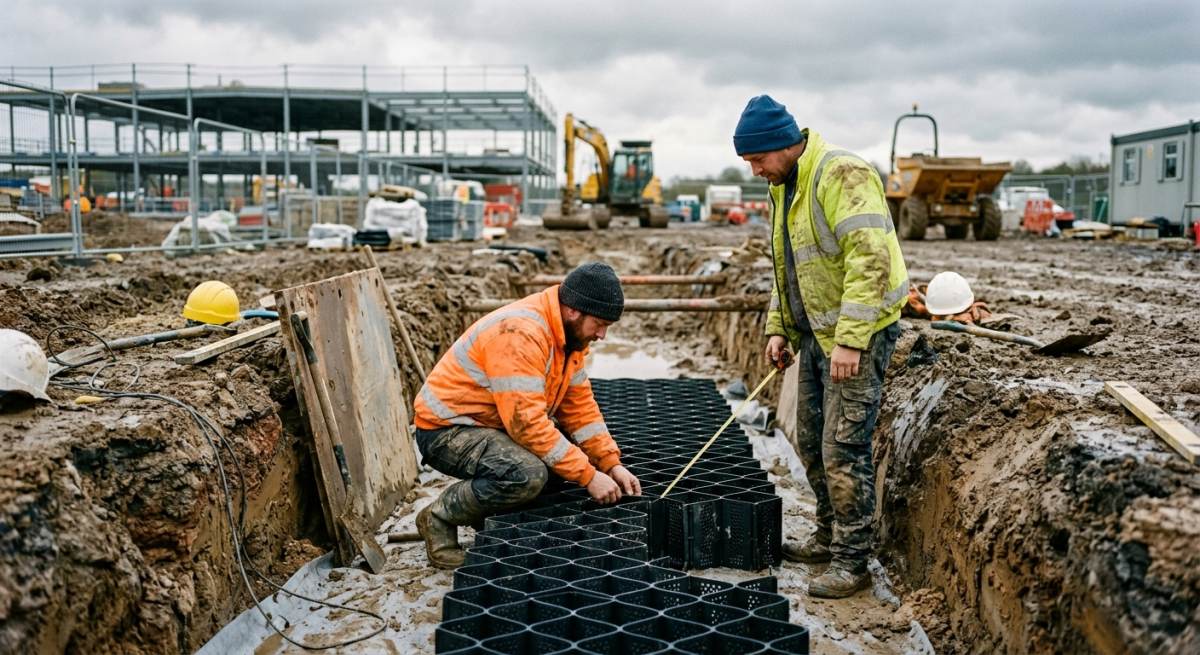
Developing brownfield sites across the UK demands a rigorous dual approach to sub-surface protection because hazardous soil gasses and liquid moisture frequently co-exist beneath foundation slabs. This section examines how structural engineers, groundworks contractors, and site designers can effectively specify combined barrier systems to mitigate atmospheric hazards and water ingress simultaneously.
Readers will learn about the precise mechanics of subterranean contamination, including harmful Ground Gas concentrations, volatile hydrocarbon vapours, and aggressive sub-surface water tables. The text details the mandatory technical alignment required between BS 8485 for ground gas protection and BS 8102 for structural waterproofing in below-ground structures. By evaluating modern dual-purpose membrane technologies, specialised drainage channels, and validated lap-sealing protocols, this section equips building project managers with practical knowledge to safeguard commercial and residential developments.
Understanding how these distinct sub-surface forces interact ensures long-term structural resilience, full regulatory compliance, and cost-effective groundworks installation without compromising safety or project delivery timelines.
Managing complex subterranean environmental risks on modern UK brownfield sites presents severe technical challenges when volatile Ground Gas hazards coincide with high Substructure Moisture levels. Project teams frequently struggle to specify robust barrier membranes that successfully resist migrating hazardous gases such as Methane or Radon while simultaneously withstanding relentless dampness beneath foundation slabs.
Failing to resolve these overlapping hazards during early design phases routinely triggers costly planning refusals and compromises structural durability, as highlighted by BS 8485 standards for ground risk management. Uncontrolled Hydrostatic Pressure coupled with unsealed gas pathways regularly forces emergency structural retrofits that escalate overall groundworks expenditure by upwards of 25%.
Fortunately, modern engineered multi-layer barrier membranes now offer a fully integrated solution designed to block both harmful soil gases and continuous liquid moisture in a single system. These advanced dual-function membranes simplify complex installation schedules, reduce site labour requirements, and deliver guaranteed regulatory compliance through a clean, cost-effective application.
KEY TAKEAWAYS
- Combined barrier membrane systems effectively protect foundation slabs against migrating Radon and Methane gases while offering complete resistance against heavy moisture.
- Structural design teams must harmonise BS 8485 gas mitigation measures with BS 8102 structural waterproofing standards to guarantee robust regulatory compliance across all build phases.
- Specifying high-performance dual-barrier membranes reduces overall site installation labour by 30% while permanently eliminating structural moisture failure risks in saturated sub-surface environments.
Technicians roll out a heavy-duty gas barrier membrane over concrete substructure footings on a residential development site in Yorkshire.
Table of Contents
- Selecting the Right Gas Barrier Membrane for Damp Conditions
- Jointing and Penetration Details in Wet Substructures
- Substrate Preparation and Protective Layers
- Verification and Integrity Testing for Specialist Installers
- Frequently Asked Questions around Gas Barrier Membrane
Need Specialist Advice on gas barrier membrane?
Speak to our technical team today for tailored specifications, regulations compliance, and practical support.
Selecting the Right Gas Barrier Membrane for Damp Conditions
Evaluating Material Composition for Dual Protection
Selecting a suitable Gas Barrier Membrane requires evaluating how well its chemical layers resist liquid water and ground gas transmission simultaneously. High-performance membranes featuring an Aluminium Foil Core laminated between layers of virgin Polyethylene Membrane provide an impermeable shield against aggressive subterranean fluids and volatile compounds.
Standard damp-proof membranes often fail in contaminated, high-moisture ground because methane and radon diffuse through basic polymers over 10 to 15 years. Incorporating a robust continuous foil layer ensures zero gas permeability while maintaining high hydrostatic head resistance across 60-year design lifespans. Engineers must verify that multi-layer composites maintain high tensile strength and puncture resistance above 450 N to prevent damage from rough sub-base aggregates during installation in deep excavations across wet sites.
These laminated systems also offer essential chemical resistance when subterranean damp contains elevated sulfate concentrations or aggressive VOC traces commonly found on brownfield plots in built-up areas.
Aligning Technical Standards for Ground Gas and Water Ingress
Specifiers must cross-reference product performance metrics against both BS 8485 for ground gas protection and BS 8102 for below-ground waterproofing. Harmonising these standards guarantees that a dual-function membrane installation satisfies strict environmental hazard codes and structural damp prevention mandates.
BS 8485 dictates site characterisation scores based on gas transmission rates, requiring verified laboratory test data for methane permeability under 40 cm³ per m² per day. Concurrently, BS 8102 classifies underground waterproofing risk, categorising sub-structure environments into Type A barrier protection styles.
Selecting a dual-certified Gas Barrier Membrane satisfies characterisation requirements for Characteristic Situation 2 through Characteristic Situation 6 sites, preventing water ingress even when water tables rise by 2 to 3 metres during intense rainfall events in low-lying areas. This dual alignment eliminates the need for separate damp-proofing sheets, saving structural depth and installation time on complex commercial builds.
Verifying Seam Integrity in High Moisture Substructures
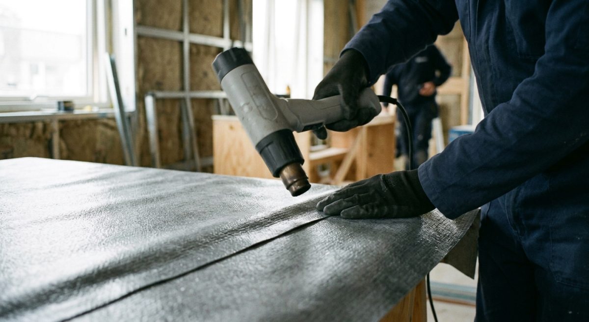
Ensuring complete seam integrity requires rigid jointing protocols tailored to wet sub-surface conditions. Thermal welding and specialised butyl tapes create continuous, gas-tight seals capable of resisting constant damp conditions without degrading over 50-year design periods.
In wet conditions, unsealed membrane laps allow moisture and hazardous soil gases to bypass structural tanking layers. To guarantee continuous protection across saturated substructures, site teams must follow a strict 3-step inspection procedure during lap jointing.
- Clean and dry all membrane overlap zones extending at least 150 mm using industrial hot-air guns to remove residual condensation.
- Apply gas-resistant double-sided tape along the seam centreline, followed by a continuous thermal twin-wedge weld.
- Conduct compressed-air needle testing along every welded lap at 2 bar pressure for 5 minutes to confirm gas-tight performance.
Technical Specification ComparisonSwipe sideways to view full table →
| Specification | Primary Features | Lifespan | Cost Bracket | Building Regulations Compliance |
| Reinforced PE Aluminium Gas Barrier Membrane | Multi-layer virgin polyethylene with integral aluminium foil core. Provides combined protection against radon, methane, carbon dioxide, and dampness in high moisture soils. | 60 years | ££ | BS 8485 2015+A1 2019, BS 8102 2022 Type A, Approved Document C |
| Liquid-Applied Hydrocarbon and VOC Gas Barrier | Seamless elastomeric liquid membrane applied directly to concrete. Ideal for complex pipe penetrations, irregular surfaces, and sites with high moisture and chemical risks. | 50 years | £££ | BS 8485 2015+A1 2019, BS 8102 2022 Type A, CIRIA C735 |
| Studded HDPE Cavity Drain Gas Membrane | High-density polyethylene cavity drain profile engineered with low gas permeability. Manages active water ingress while creating an internal void for ground gas pressure relief. | 50 years | ££££ | BS 8102 2022 Type C, BS 8485 2015+A1 2019, Approved Document C |
| Self-Adhesive Polymer Modified Bitumen Gas Membrane | Heavy-duty bitumen compound laminated to a cross-laminated polyethylene carrier film. Excellent puncture resistance and self-healing properties for damp underground substructures. | 60 years | £££ | BS 8485 2015+A1 2019, BS 8102 2022 Type A, Approved Document C |
Jointing and Penetration Details in Wet Substructures
Lap Joints in High Moisture Environments
Lap Joints require dual-sealing mechanisms to prevent both gas migration and hydrostatic water ingress in wet substructures. Combining double-sided Butyl Tape with continuous Thermal Welding creates a resilient barrier capable of withstanding constant hydrostatic pressure.
In sub-surface basements and ground-slabs across UK building sites, moisture compromises standard single-layer seals. Site operatives must ensure a minimum 150mm overlap between membrane sheets before applying jointing materials. Proper surface preparation ensures that ground moisture does not prevent adhesion or joint stability during initial placement.
While double-sided Butyl Tape provides an immediate vapour-tight bond, high-moisture conditions make secondary thermal fusion essential. Hot-air Thermal Welding fuses the polyolefin layers into a single continuous sheet, ensuring ground gases like radon or methane cannot bypass the damp-proofing barrier. This dual-action approach maintains structural integrity across a 60-year design lifespan, even when submerged under a 3-metre head of groundwater.
Sealing Pipe Penetrations Against Gas and Water
Sealing Pipe Penetrations in wet sub-surface conditions demands pre-formed top hats and heavy-duty elastomeric seals. Applying a Self Adhesive Membrane around service entries guarantees a gas-resistant and water-tight seal against liquid head pressure.
Service entries present the highest risk of detailing failure in high-moisture substructures. Damp conditions reduce standard adhesive performance, meaning installers must prepare surfaces meticulously before applying critical jointing components. Failure to isolate pipe collars creates pathways for hazardous ground gases to seep into occupied spaces above. Soil pipes, water mains, and cable ducts require robust mechanical protection alongside chemical adhesion. To guarantee protection against 100% relative humidity, operatives should follow a rigorous 3-step sequence.
- Clean the pipe surface thoroughly and apply a high-tack primer onto the surrounding concrete substrate.
- Fit a pre-formed gas-resistant top hat collar over the pipe, securing the base flange with Butyl Tape and stainless steel jubilee clips.
- Overwrap the entire detail using a bitumen-backed Self Adhesive Membrane, extending at least 150mm beyond the collar footprint to form a dual-barrier seal.
Continuity Testing Protocols for Wet Sites
Continuity testing verifies that combined gas and damp-proofing barriers remain fully air-tight and water-tight prior to backfilling. Non-destructive spark testing and air pressure testing isolate microscopic voids along welded seams quickly.
Substructure membranes frequently suffer damage from follow-on trades or high water tables before concrete placement. Visual inspections miss sub-millimetre pinholes, making physical testing a standard requirement on modern developments. High-voltage spark testing draws an electrical current across the membrane surface, instantly detecting gaps in welded Lap Joints.
Alternatively, twin-wedge seam welding allows direct air-pressure testing inside the central channel between double welds. Holding a constant test pressure of 2 bar for 5 minutes confirms complete joint integrity across the entire sub-surface footprint. Prompt repair of identified defects protects the substructure from long-term moisture penetration and expensive remedial works.
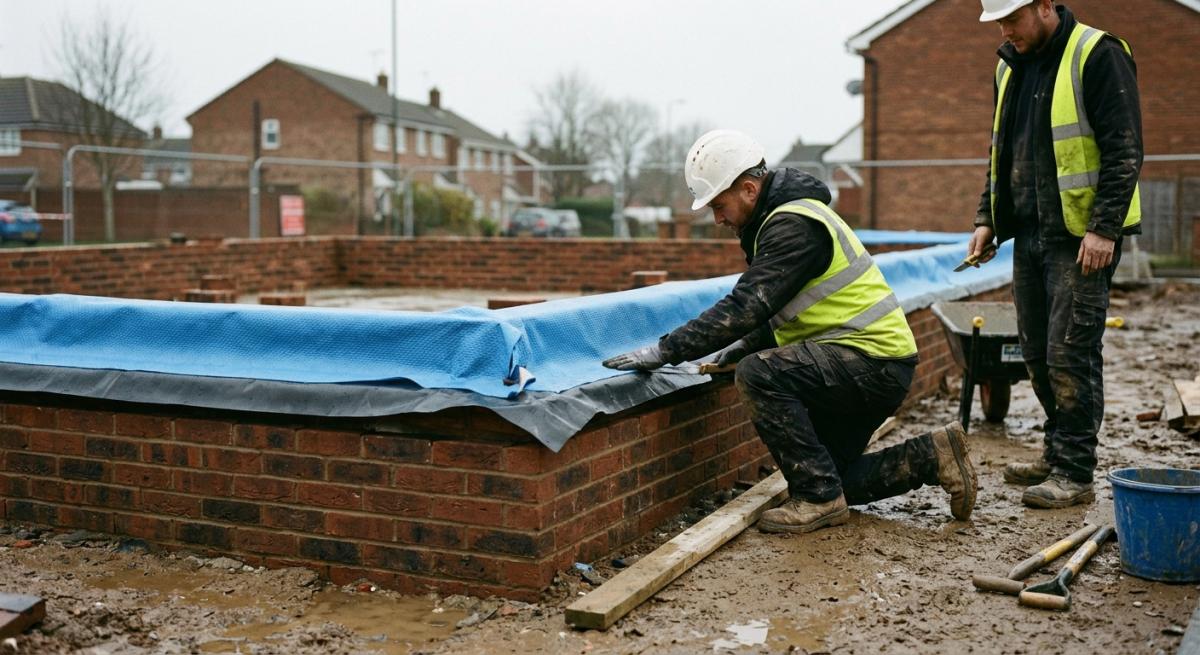
A dual-purpose waterproofing and gas barrier system undergoing installation along damp substructure walls in northern England.
Substrate Preparation and Protective Layers
Substrate Preparation for Sub-Surface Membranes
Proper Substrate Preparation removes sharp detritus and smooths irregular masonry to prevent physical tears in barrier layers. Achieving a uniform surface ensures complete contact between the damp proofing medium and the structural base.
Before laying membrane systems, structural engineers must specify a smooth bed across compacted hardcore or soil bases. Applying a 50 mm layer of Blinding Concrete creates a flat, stable platform that eliminates sharp protrusions from crushed stone aggregate. Operatives should clear away all loose rubble, standing water, and surface dust prior to pour operations.
When dealing with brickwork or contiguous piled walls, applying a 10 mm flush render coat fills deep mortar joints and smooths rough masonry faces. Removing surface ridges greater than 2 mm prevents localised point loading on gas barriers, protecting the underlying damp-proofing layout from pre-installation stress. In wet ground, engineers often specify rapid-setting screeds to accelerate readiness and keep construction schedules moving efficiently.
Protective Layers and Puncture Resistance Enhancement
Protective cushion layers guard sensitive gas barriers against aggregate impact and trade damage during subsequent concrete pours. High-performance cushioning maintains overall system integrity throughout the construction lifecycle.
Gas membranes and damp-proof barriers face extreme mechanical stress during steel reinforcement placement and concrete placement. Specifying a heavy-duty Geotextile Fleece both above and below the primary membrane dramatically improves overall Puncture Resistance. A 300 g per square metre non-woven polypropylene fleece absorbs severe impact forces from dropped tools and heavy rebar foot traffic.
In high-moisture sub-surface conditions, this cushion layer also aids water dispersal away from delicate lap joints, preventing localised hydrostatic pressure build-up. Additionally, securing protection fleeces with heavy-duty tape prevents displacement during windy conditions or rapid concrete pours.
Sequential Inspection Routine for Substructure Protection
Rigorous stage-by-stage site checks identify void formations and physical defects before concrete encasement hides them. Following a strict evaluation sequence minimizes the risk of post-construction water or gas ingress.
To ensure successful barrier installation, site supervisors must perform a 3-step verification process across every plot
- Verify that cured Blinding Concrete features no sharp aggregate exposure or unfilled surface voids exceeding 2 mm in depth.
- Inspect installed Geotextile Fleece layers for 150 mm joint overlaps and clean alignment before laying the main gas barrier.
- Perform a 100% visual and electronic spark test across all sealed seams to confirm total gastight performance before final concrete casting.
Conducting these systematic quality audits prevents costly remediation works after structural slabs are cast, securing long-term durability for 60-year building design lifespans.
Verification and Integrity Testing for Specialist Installers
Verification Plan Standards and Compliance Guidelines
A robust Verification Plan defines the precise testing protocols and quality control measures required to guarantee a sub-surface barrier performs correctly. Implementing these standards ensures that both ground-gas and moisture protection measures satisfy strict UK regulatory requirements across complex foundation schemes.
To achieve full compliance, the Specialist Installer must adhere strictly to guidance outlined in CIRIA C735. This national code of practice establishes an independent framework for validating gas-resistant membranes across brownfield sites and high-risk urban locations.
Designing a project-specific quality scheme prevents costly remediation work by identifying membrane punctures, inadequate seam laps, and joint failures prior to pouring structural concrete slabs.
Essential Integrity Testing Techniques for Gas Protection
Non-destructive Integrity Testing identifies microscopic pinholes and unsealed lap joints across installed barrier systems. Employing these advanced diagnostic methods guarantees that combined gas protection and damp-proofing layers form a completely continuous, airtight seal across 100% of the footprint.
Specialist teams rely on 3 primary field-testing routines to evaluate sub-surface membrane installations.
- Trace-gas testing using inert, non-flammable tracer gas mixtures beneath the sheet to pinpoint micro-leaks along complex foundation details.
- High-voltage dielectric spark testing along welded seams to detect physical breaches, pinholes, and void spaces in elastomeric materials.
- Low-pressure air-testing or smoke-testing procedures beneath mechanically fixed membranes to provide immediate visual confirmation of seal continuity around service pipe penetrations.
Executing these rigorous routines before placing reinforcement steel gives structural engineers absolute confidence in long-term performance.
Visual Inspection Procedures and Specialist Installer Sign Off
Thorough Visual Inspection provides the foundational layer of site validation before any non-destructive testing takes place. A qualified Specialist Installer conducts these systematic site checks to confirm correct lap dimensions, mechanical fixings, and adequate surface preparation across all ground-bearing slabs.
The inspector logs every observation onto a comprehensive QA checklist to create an auditable paper trail for building control officers and warranty providers. Physical audits focus heavily on high-stress zone detailing, including internal corners, pile caps, lift pits, and step-downs where double-sided butyl tapes or continuous thermal welds secure the membrane barrier.
Critical site inspection checkpoints include * Verifying 150 mm minimum lap overlaps across all damp-proofing and gas-resistant barrier sheets. * Confirming that all sub-surface concrete substrates remain smooth, dry, and free from abrasive debris or sharp aggregate projections. * Reviewing thermal weld test strips prepared at the start of each working shift to verify bond strength. * Signing off completed installation sign-off sheets to validate compliance against CIRIA C735 standards.
A specialist contractor heat-welds lap joints to ensure a gas-tight seal over damp proofing layers in high-moisture sub-floors.
Frequently Asked Questions around Gas Barrier Membrane
What Is a Gas Barrier Membrane in Substructure Waterproofing?
A gas barrier membrane is a specialised sheet material designed to block harmful ground gases such as radon, methane, and carbon dioxide from entering a building through the foundations. When installed in high-moisture substructures, it often performs a dual role by stopping both hazardous ground gases and liquid water or rising damp.
Can a Gas Barrier Membrane Replace a Standard Damp Proof Membrane?
Yes, a gas barrier membrane can replace a standard damp-proof membrane if it carries the correct technical ratings for both water tightness and gas resistance. Most modern gas-resistant membranes are manufactured from heavy-duty polymers that exceed the performance standards of basic damp-proof sheets.
However, you must ensure that all joints are sealed with gas-tight tape or fully welded to maintain protection against both ground water and dangerous fumes.
How Do You Seal Joints When Combining Gas Membranes with Damp Proofing?
You seal joints using double-sided butyl tape combined with a gas-resistant top tape, or by thermal welding the overlaps. Standard duct tape or basic damp-proofing tape is not suitable because ground gases can easily pass through weak seals.
Overlaps should be at least 150mm wide to ensure a durable, water-tight bond across the entire sub-surface area.
Which Ground Gases Require a Dedicated Gas Barrier Membrane?
Radon, methane, carbon dioxide, and volatile organic compounds require a dedicated gas barrier membrane to protect building occupants. Sites with a high risk of ground contamination, such as former industrial land or areas near landfills, always require specialist membranes tested to British Standard BS 8485.
Does a Gas Barrier Membrane Need to Be Laid Above or Below the Concrete Slab?
A gas barrier membrane can be laid either above or below the concrete slab depending on the structural design and site conditions. Placing the membrane below the slab offers early protection to the concrete, while installing it above the slab reduces the risk of puncture damage during construction.
What Thickness Is Required for an Effective Gas Barrier Membrane?
An effective gas barrier membrane generally requires a minimum thickness of 0.4mm for virgin polyethylene sheets, though reinforced or aluminium-foil membranes can be thinner while offering higher protection. Thickness alone does not guarantee performance, so you must verify the material gas-permeability rating against local building regulations.
How Do High Moisture Levels Affect the Performance of Gas Membranes?
High moisture levels do not degrade high-quality gas barrier membranes, but trapped standing water can make joint sealing more difficult during installation. Sub-surface water pressure can also force moisture through unsealed laps if the membrane is not correctly integrated with the damp-proofing system.
What Is the Typical Lifespan of a Sub-surface Gas Barrier Membrane?
The typical lifespan of a correctly installed gas barrier membrane matches the design life of the building, which is usually 60 years or more. High-density polymers resist chemical breakdown from soil pollutants and water contact over 100% of their operational life.
Can Gas Barrier Membranes Be Punctured Easily During Installation?
Unprotected gas barrier membranes can be punctured by sharp aggregate, steel rebar, or heavy foot traffic during the build process. To prevent damage, contractors should install a protective fleece or screed layer over the membrane within 24 hours of laying it.
Are Third-party Certifications Necessary for Gas Barrier Membranes in High Moisture Areas?
Yes, third-party certifications such as BBA approval are essential to confirm that the membrane blocks both ground gases and water penetration. Building control inspectors will require documented proof of compliance before sign-off on 100% of high-risk sites.
Ready to Discuss Your gas barrier membrane Project?
Get in touch with our specialists today for detailed site guidance, technical specifications, and a quotation tailored to your requirements.