Installing an effective ground gas barrier across complex sub-surface details requires strict adherence to British compliance frameworks. This section outlines the regulatory landscape that governs gas protection design in modern developments across every town and city. Site investigations frequently detect harmful sub-surface contaminants like Methane and Carbon Dioxide, which pose severe health and safety risks if allowed to migrate into occupied spaces.
Developers must navigate rigorous codes of practice to gain planning approval and satisfy local authority building control officers across the UK. We examine how BS 8485 dictates the minimum characterising points required for gas protection systems, alongside independent validation frameworks outlined in CIRIA C735. Special focus is given to high-risk junction points, such as service pipe penetrations and structural columns, where design oversights often compromise the overall membrane continuity. Mastering these regulatory requirements ensures long-term structural integrity, protects future occupiers, and guarantees full compliance across 100% of brownfield and greenfield construction projects.
Securing building control sign-off for complex foundation details often stalls when developers fail to prove total gas-tight integrity around awkward sub-surface service entries. Fitting a continuous ground gas barrier around intricate pipe penetrations and structural columns creates severe technical hurdles for site contractors operating under tight construction schedules.
Without independent verification carried out under CIRIA C735, minor punctures or poorly sealed top-hat boots trigger costly project delays and full planning refusals. Indeed, non-compliant detail sealing accounts for up to 70% of ground-gas protection failures on UK sites, leading to remediation bills that easily exceed £20000 per plot.
Deploying pre-formed sleeves and flexible liquid-applied membranes resolves these complex penetration details cleanly, quickly, and cost-effectively. Aligning these robust materials with the precise scoring metrics in BS 8485 ensures complete resistance against toxic Methane and Carbon Dioxide gas ingress for the entire 60-year design life of the building.
KEY TAKEAWAYS
- Correctly characterising site gas regimes under BS 8485 ensures your chosen ground gas barrier achieves the exact minimum point score needed for seamless planning approval.
- Independent installation verification following CIRIA C735 guidelines prevents expensive retrofits, satisfies building control officers, and permanently blocks Methane and Carbon Dioxide pathways.
- Combining pre-engineered top-hat seals with liquid-applied gas membranes delivers a fast, cost-effective method for achieving continuous protection around complex penetrations and structural columns.
Table of Contents
- Key Physical Challenges at Pipe Penetrations
- Step by Step Method for Sealing Service Pipes
- Navigating Complex Steelwork and Structural Columns
- Selecting Between Preformed Sleeves and Liquid Applied Systems
- Verification and Quality Control Requirements on Site
- Frequently Asked Questions around Gas Membrane Installation
Need Specialist Advice on gas membrane installation?
Speak to our technical team today for tailored specifications, regulations compliance, and practical support.
Key Physical Challenges at Pipe Penetrations
Managing Complex Geometry and Tight Spaces
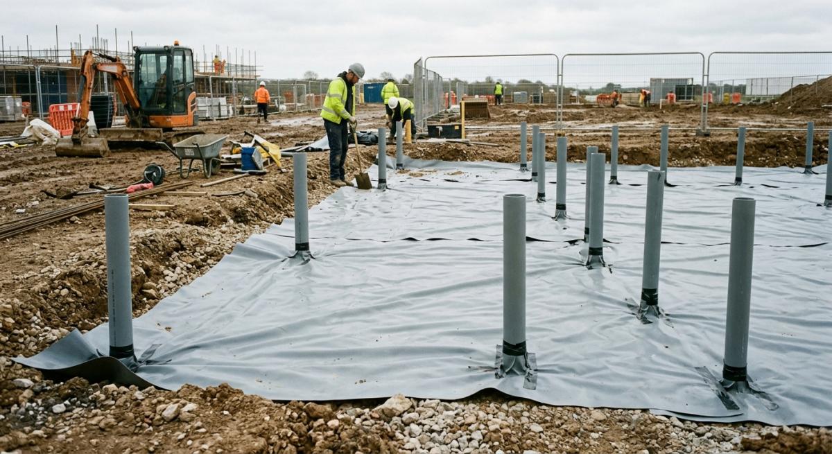
Sealing a Pipe Penetration requires adapting rigid sheet membranes to irregular round profiles in constrained sub-surface voids. Installers must use pre-formed components like a Top Hat Sleeve to create a robust junction where flat sheets fail to conform smoothly. Ground gas membranes arrive on site as heavy rolls designed primarily for wide, uninterrupted slab areas.
When facing clustered utility services in dense town developments, cutting flat sheets to fit tight contours creates significant risk of micro-gaps. Pinhole tears frequently occur around 110 mm soil pipes or service entries spaced less than 300 mm apart. Using a flexible Pipe Collar alongside a manufactured Top Hat Sleeve resolves these geometric constraints by transferring the critical gas-tight bond away from the cluttered floor interface up onto the vertical pipe wall.
Accommodating Sub-surface Differential Settlement
Relative movement between structural ground slabs and buried utility lines creates strong shear stresses on ground gas membranes. Without built-in flexibility, Differential Settlement can tear membrane material away from the pipe circumference over a 60-year building lifespan.
Sub-soil movement rarely occurs uniformly across a 100% concrete ground footprint. As surrounding fill settles by 10 mm to 25 mm, rigid drain lines remain anchored to deep pile foundations, pulling directly against the surrounding barrier membrane. To guarantee ongoing protection, site teams must implement a structured movement sealing procedure:
- Verify a minimum 150 mm lap width between the primary floor membrane and the flexible Pipe Collar flange.
- Check that high-tack double-sided jointing tape is rolled and compressed uniformly around the 360 degree pipe circumference.
- Apply a flexible gas-resistant liquid detail or elastomer patch across the seam edge to absorb up to 20 mm of lateral shear.
Ensuring Defect-Free Sealing Protocols
Contaminated ground gas easily migrates through 1 mm tears in compromised seal perimeters under modest sub-surface pressures. Achieving effective gas resistance demands thorough surface preparation and purpose-engineered detailing accessories. Construction dust, standing rainwater, and site mud destroy self-adhesive bond lines within 5 minutes of open exposure.
If installers apply self-adhesive butyl tapes directly to uncleaned plastic pipework, hazardous soil gases like methane and carbon dioxide will track through micro-passages in the joint. Thoroughly wiping pipe walls with solvent cleaner, applying targeted quick-drying primers, and dressing complex junctions with liquid-applied gas membranes ensures a continuous barrier across 100% of high-risk penetration points. It also eliminates reliance on manual taping in restricted angles where hand pressure cannot be applied evenly. This multi-layered sealing approach guarantees long-term protection for modern structural foundations.
Step by Step Method for Sealing Service Pipes
Sub-Surface Preparation and Penetration Assessment
Achieving a gas-tight seal around service pipes requires meticulous cleaning and precise membrane dress-back before applying any dynamic detailing products. Eliminating debris and standing water ensures robust adhesive bonding across all ground-level entry points. Ground gas entry typically occurs at weak interface points, making preparation the most critical phase of subterranean gas proofing.
Site teams must clear away dirt, concrete slurry, and grease from pipe surfaces within 300 mm of the slab interface. The main Gas Resistant Membrane must lay perfectly flat around the pipe penetration, cut cleanly without jagged tears or excessive gaps exceeding 10 mm. Rough concrete surrounds ought to be smoothed with quick-setting repair mortar to create a clean, level plane. Leaving loose aggregates or standing water near the pipe penetration will compromise adhesive tapes and lead to premature barrier failure under structural settlement.
3 Step Top Hat Collar Installation Sequence
Installing a dedicated collar system provides mechanical and adhesive defence against hazardous soil gas migration at structural pipe penetrations. This standardised method guarantees continuous gas-proof coverage even when sub-base movement occurs over a 60-year building design life. Deploying manufactured components streamlines installation quality across complex, high-density service clusters on modern construction sites.
- Apply a continuous ring of high-performance Double Sided Butyl Tape around the cleaned service pipe base and the underlying Gas Resistant Membrane lap zone.
- Slide the flexible Preformed Top Hat sleeve over the utility pipe, pressing its circular apron firmly onto the prepared tape to form a broad 150 mm bonded joint.
- Secure the upright sleeve of the unit to the utility pipe using a heavy-duty Stainless Steel Jubilee Clip tightened to 4 Nm torque to prevent gas bypass.
Quality Assurance and Continuity Verification
Rigorous visual inspection and non-destructive testing confirm that the installed sleeve assembly remains completely air-tight and gas-resistant. Systematic verification prevents expensive remedial works after concrete pours conceal critical ground-gas barriers. Modern risk management frameworks demand documented proof of barrier integrity before sign-off.
Site engineers should visually inspect every joint for continuous tape adhesion and check mechanical fixing tension across 100% of service entries. Any minor voids or overlaps under 50 mm require immediate hot-air welding or targeted butyl patching to guarantee site safety compliance across all built-up area developments.
Non-destructive air-lance testing at 100 kPa pressure or seam probe testing helps identify hidden micro-voids prior to placing floor screeds or structural reinforcement steel. Documenting each completed pipe penetration with photographic evidence provides a 100% verifiable audit trail for local authority building control officers.
Navigating Complex Steelwork and Structural Columns
Sealing Around the Steel Base Plate
Sealing the steel base plate requires a robust detailing approach to prevent hazardous ground gases from bypassing the primary barrier system. Applying a Liquid Applied Gas Barrier ensures an airtight, seamless bond across irregular metal fixings and concrete foundations.
Steel footings present awkward geometric profiles, holding-down bolts, and levelling shims that conventional sheet membranes cannot easily accommodate. Sheet membranes must overlap the sub-surface concrete pad by at least 150 mm before terminating near the steelwork. To seal these intricate shapes, site teams brush or spray a thick coat of Liquid Applied Gas Barrier over the pre-primed steel and surrounding sheet interface.
This elastomeric liquid compound cures into a tough skin covering 100% of surface irregularities, protecting structural foundations across a 60-year lifespan without leaving pinholes or air gaps.
Integrating Membrane Flanges at the Structural Column
Integrating flexible membrane skirts around each structural column maintains continuous gas protection where rigid materials fail. Installers must dress a self-adhesive membrane neatly over the joint to absorb structural movements and differential settlement stresses.
Placements around an H-section or square structural column demand meticulous hand-crafting of membrane collar flanges on site. Standard flexible sheet membranes are dressed tightly to vertical steel faces, then reinforced with a high-performance self-adhesive membrane detail patch. This double-layer method isolates sub-surface structural junctions from shear forces while keeping gas migration pathways completely blocked across local streets and commercial developments.
Follow this 3-step installation sequence for column intersections:
- Clean and prime all steel surfaces to 300 mm above slab level using a quick-drying primer.
- Form tight gusset corners using self-adhesive membrane fillets overlapping the main sheet by 100 mm.
- Encapsulate the entire collar junction with a cold-applied liquid top coat to guarantee a gas-tight seal.
Verification and Quality Control Procedures
Independent verification ensures every complex structural detail satisfies stringent gas safety standards before concrete placement. Visual inspection combined with non-destructive integrity testing guarantees the long-term effectiveness of the gas barrier.
Gas protection systems installed across any built-up area construction site must undergo rigorous quality assurance protocols before sign-off. Integrity testing around columns identifies invisible tears, mechanical puncture damage, or unbonded lap edges caused by follow-on trades working on site.
- Visual check, verify 100% of lap widths, seal continuity, and physical fixings.
- Point-probe testing, trace all seam edges using a blunt probe to detect unbonded laps.
- Air lance or spark testing, test high-risk seals around steel fixings for microscopic breaches.
Selecting Between Preformed Sleeves and Liquid Applied Systems
Standardising Singular Penetrations with a Preformed Boot
Preformed boot components offer maximum reliability for standard circular pipe penetrations through ground-gas barrier layers. These factory-manufactured units reduce site-labour risks by providing guaranteed material thickness across simple geometries.
When dealing with isolated 110 mm or 160 mm plastic soil pipes, selecting a factory-made preformed boot accelerates site-installation schedules. The pre-moulded profile eliminates complex hand-welding on site, creating a robust seal that complies with BS 8485 design requirements. Site teams can rapidly complete these penetrations using a straightforward 3-step sequence.
- Clean the sub-surface pipe wall and surrounding gas membrane with a solvent cleaner.
- Slide the preformed boot over the pipe and bond the base flange using heavy-duty gas-resistant tape.
- Secure the upper neck with a stainless-steel jubilee clip and a bead of cold-applied sealant.
Resolving Complex Geometry using Liquid Membrane Formulations
A brush or spray-applied liquid membrane provides a seamless gas barrier around irregular structural columns and non-circular penetrations. This cold-applied technology bonds directly to steel, concrete, and masonry, eliminating void spaces where hazardous gas might accumulate.
Structural steel H-beams and concrete column bases present awkward profiles that sheet membranes cannot encapsulate cleanly. Cutting and taping sheet membranes around steel flanges creates dozens of linear joints, significantly raising the risk of long-term gas ingress. An elastomeric liquid membrane flows easily around sharp corners, holding bolts, and baseplates, curing into a continuous barrier layer. Site operatives typically apply 2 separate coats to achieve a uniform 2 mm dry-film thickness across all exposed faces. Before applying, installers place a fillet of cold-applied sealant around the internal base angle to eliminate 90-degree corners and reduce movement stress.
Managing Tight Spatial Tolerances in a Cluster Penetration
A cluster penetration requires a fluid liquid system because tight pipe spacing prevents the correct fitting of rigid collar profiles. Attempting to fit multiple preformed units within a crowded duct entry creates unsealable gaps and compromises the gas barrier integrity.
In modern plant rooms and central service ducts, multiple utility pipes frequently pass through concrete floor slabs with less than 50 mm clearance between conduits. In these congested conditions, standard sheet overlaps cannot form a gas-tight seal.
Pouring or brushing a flexible liquid membrane across the entire pipe array coats every hidden surface, sealing intricate voids where rigid boots fail. Project managers often specify this hybrid approach to guarantee continuous protection across high-density service entries on busy construction sites.
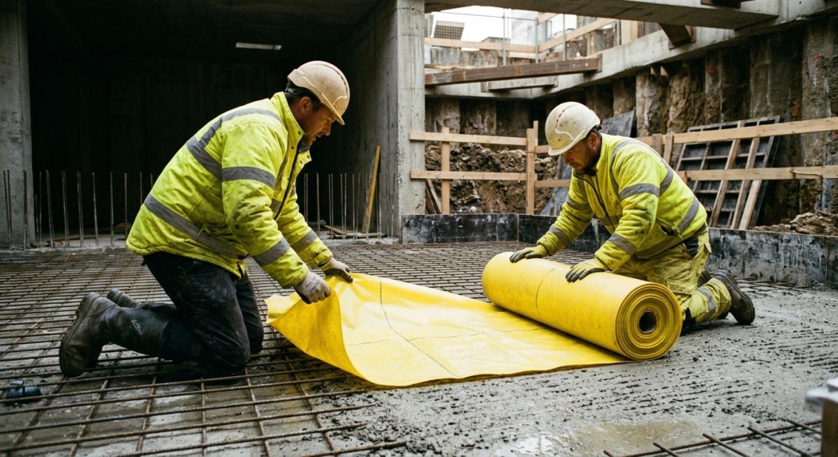
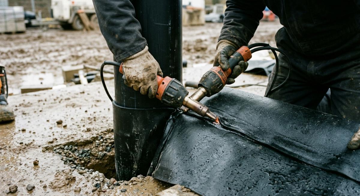
Heat-welding pipe penetration sleeves creates a verified airtight seal against hazardous ground gases.
Verification and Quality Control Requirements on Site
The Role of Independent Verification
Independent verification guarantees that ground gas protection systems comply fully with design specifications and British standards. Engaging a qualified Independent Verifier ensures unbiased assessment before concrete pours obscure high-risk details.
Under CIRIA C735 guidelines, verification must occur continuously throughout the construction timeline rather than as a single sign-off event. Independent verifiers assess site-specific risk levels, check material compatibility, and sign off membrane placement around complex geometry.
When dealing with ground gas membranes near pipe penetrations and universal column bases, an independent reviewer provides objective oversight that prevents costly post-construction remediation work. This independent oversight protects building owners by ensuring installer competency and maintaining a clear audit trail for local authority building control approval.
Visual Inspection Protocols for Penetrations
Visual Inspection forms the initial baseline assessment for every complex structural column and pipe boot detail. Competent inspectors check membrane continuity, overlap dimensions, and seal integrity across all sub-surface joints.
A rigorous visual check routine follows a strict 3-stage sequence prior to covering any sub-surface detailing.
- Inspect raw substrate preparation to confirm 0 sharp edges or debris threaten the membrane near penetrations.
- Verify a minimum lap width of 150 mm across all pre-formed pipe collars and column patches.
- Confirm double-sided gas-resistant tape or hot-wedge welds display continuous, uniform bonding with 0 air pockets.
Where pipe penetrations sit within 300 mm of structural columns, visual checks identify tight geometry where standard tools struggle. Inspectors record all findings using geotagged photography and structured reporting forms, flagging any defective areas for immediate repair before secondary testing occurs.
Non-Destructive Integrity Testing Techniques
Integrity testing provides empirical evidence that complex membrane welds around penetrations remain completely gas-tight. Non-destructive methods validate seam strength without compromising the protective barrier underneath foundation slabs.
While visual checks catch gross defects, micro-fine leaks around pipe sleeves demand advanced physical challenge methods. Techniques like dielectric spark testing, air lance testing, and tracer gas detection pinpoint pinhole failures invisible to the naked eye. Spark testing passes a high-voltage current across non-conductive membrane joins, creating a visible electric arc whenever a gap exists.
Air lance testing directs a focused jet of compressed air at 100 kPa along lap edges to reveal unbonded sections instantly. Deploying these methods under CIRIA C735 frameworks ensures 100% of critical column and pipe seals withstand long-term sub-surface gas pressures.
Frequently Asked Questions around Gas Membrane Installation
What Is a Ground Gas Membrane and Why Is It Necessary?
A ground gas membrane is a specialised sub-surface barrier designed to prevent hazardous ground gases such as radon, methane, and carbon dioxide from entering a building. It is necessary on brownfield sites or development areas with high gas risks to protect occupants from toxic fumes and explosion hazards over a 60-year building lifespan.
How Do You Seal Ground Gas Membranes Around Pipe Penetrations?
Sealing a ground gas membrane around a pipe penetration requires pre-formed top-hat sleeves, double-sided gas-resistant tape, or self-adhesive gas-proof seals. You must clean the pipe surface thoroughly before heat-welding the joints or applying gas-tight patches to achieve a 100% airtight seal.
What Special Steps Are Required when Installing Gas Membranes Around Structural Columns?
Installing a gas membrane around a structural column requires custom-fitted collar details secured with double-sided gas-resistant tape and mechanical clamping bars. The sheet membrane must be dressed neatly around complex column bases and combined with liquid-applied gas membranes to seal irregular structural shapes.
Which British Standards Apply to Gas Membrane Installation?
The primary British standard governing gas membrane installation is BS 8485, which defines the code of practice for ground gas protection in new buildings. Installers must also follow CIRIA C735 guidelines to ensure correct quality assurance and independent verification on every site.
Can Liquid-Applied Membranes Be Used Around Complex Pipe Networks?
Yes, liquid-applied ground gas membranes are ideal for sealing around complex or tightly grouped pipe penetrations where sheet membranes cannot fit. These liquid products cure to form a continuous, seamless, gas-resistant layer that bonds directly to plastic or concrete pipes.
How Are Joints and Seams Tested During Gas Membrane Installation?
Joints and seams are tested using non-destructive methods such as air-lance testing, probe testing, or tracer-gas testing. An independent verifier performs 100% visual checks alongside targeted mechanical probe tests to confirm that every lap joint remains fully gas-tight.
What Minimum Lap Width Is Required for Gas Membrane Sheets?
A minimum lap width of 150 mm is required for heat-welded gas membrane sheets, whereas taped joints typically require 150 mm to 200 mm overlaps. Maintaining these exact dimensions ensures a durable, gas-resistant seam across the entire floor area.
What Are the Most Common Failures in Gas Membrane Installation?
The most common failures occur due to puncture damage from site traffic, uncleaned surfaces during welding, and poorly sealed pipe penetrations. Installing heavy-duty protection boards and inspecting 100% of the membrane prior to pouring concrete prevents 90% of these physical defects.
Who Is Qualified to Install and Inspect Ground Gas Barriers?
Ground gas barriers must be installed by NVQ Level 2-qualified specialists and inspected by an independent, NVQ Level 4-qualified gas protection verifier. This 2-stage verification process ensures full compliance with British building regulations and site-specific design plans.
How Long Does a Properly Installed Gas Membrane Last?
A properly installed, high-quality ground gas membrane will last for 60 years or the design life of the building. Protecting the installed barrier from sunlight exposure and physical site damage ensures that its gas-resistant properties will not degrade over time.