Managing surface water management effectively across modern development sites requires a clear, structured framework that balances flood risk with environmental protection. The SuDS Manual, formally published as CIRIA C753, serves as the definitive reference point for civil engineers, local authorities, and site developers across the UK. By shifting the focus away from traditional piped drainage towards holistic Sustainable Drainage Systems, these robust guidelines dictate how modern attenuation tanks are calculated, designed, and installed.
Understanding the core principles of CIRIA C753 is fundamental to ensuring your attenuation schemes meet strict water quality targets, deliver long-term structural integrity, and gain swift approval from lead local flood authorities. With over 30 years of hands-on experience, Catalogue Engineering provides the specialist installation expertise needed to turn these rigorous technical standards into dependable, real-world drainage assets.
Navigating complex surface water management regulations often creates significant friction for site managers attempting to secure drainage sign-offs on tight schedules. Conflicting design interpretations between civil engineers and local approving bodies routinely lead to costly redesigns and frustrating site delays.
Without a unified framework, miscalculated storage volumes or poorly selected attenuation systems risk early structural failure and severe localised flooding. These avoidable errors drain project budgets, damage commercial reputations, and trigger hefty remedial costs during the post-construction phase.
Adopting the clear criteria set out in the SuDS Manual streamlines the entire design process while guaranteeing compliance with modern statutory standards. Integrating expert guidance on CIRIA C753 ensures attenuation tanks deliver optimal hydraulic performance and lasting environmental benefits for every development.
KEY TAKEAWAYS
- CIRIA C753 provides the ultimate best-practice framework for designing, specifying, and maintaining sustainable drainage systems across UK developments.
- Modern attenuation tank designs must balance four core pillars, including water quantity, water quality, amenity, and biodiversity, to secure planning approval.
- Partnering with specialist installers ensures underground attenuation systems satisfy all structural and hydraulic requirements defined within the SuDS Manual.
Table of Contents
- Core Role of Attenuation Tanks in Modern Water Management
- Structural Design Criteria According to CIRIA Guidelines
- Water Quality and Treatment Train Integration
- Membrane Selection and Waterproofing Best Practice
- Long Term Maintenance and Asset Protection
- Frequently Asked Questions around Attenuation Tank
Need Specialist Advice on attenuation tank?
Speak to our technical team today for tailored specifications, regulations compliance, and practical support.
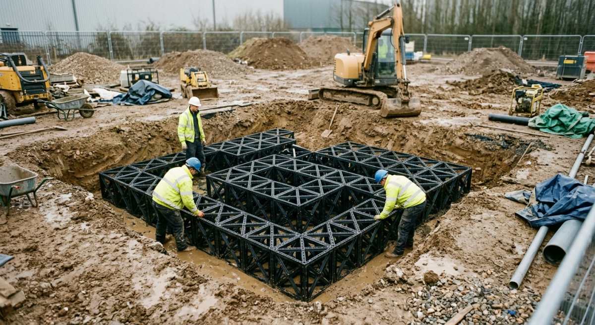
Core Role of Attenuation Tanks in Modern Water Management
Attenuation tanks form the backbone of modern drainage infrastructure by capturing heavy rainfall before it can overwhelm local drainage networks. These robust subsurface systems hold excess water temporarily and release it at a controlled rate back into natural watercourses or sewer networks.
Managing surface water during heavy storms
Modern attenuation tanks provide a dependable buffer that prevents surface water from flooding nearby properties during intense downpours. By collecting massive volumes of runoff from roofs and paved surfaces, these units protect local communities when weather conditions turn severe.
As built environments expand, natural ground absorption decreases. Without dedicated storage solutions, heavy rainfall quickly overloads traditional infrastructure. Attenuation tanks bridge this gap by holding water safely underground until downstream channels have the capacity to process it.
Delivering precise peak flow control
Peak flow control relies on restricting the discharge rate of stored rainwater using specialised flow control devices. This regulated release ensures that receiving watercourses experience a steady, manageable flow rather than a sudden, damaging surge.
To establish an effective discharge strategy, engineers typically follow a straightforward 3-step process.
- Calculate the pre-development greenfield runoff rate for the site.
- Position precision flow control valves or orifice plates at the tank outlet.
- Monitor long-term discharge performance to prevent downstream erosion.
By maintaining this balance, developers meet stringent local planning conditions while protecting surrounding habitats from scour and bank destabilisation.
Supporting sustainable stormwater storage strategies
Stormwater storage plays an essential role in holistic water management by aligning site drainage with broader environmental targets. Integrating well-designed attenuation units into wider SuDS schemes helps replicate natural hydrological processes across commercial and residential developments.
With over 30 years of experience as specialist installers, the team at Catalogue Engineering integrates high-performance attenuation tanks into complex site layouts. Proper attenuation strategy reduces flood risk, minimises pollution risks, and supports long-term structural resilience for the surrounding built environment.
| Attenuation System Type | CIRIA C753 Water Quality Alignment | Structural Integrity and Void Ratio | Maintenance Access Requirements | Primary Site Application |
|---|---|---|---|---|
| Modular Geocellular Crates | Requires upstream treatment trains such as silt traps or bio-retention to prevent sediment build up inside the matrix | High void ratio up to 95 percent with tailored loading capability from light domestic to heavy traffic zones | Requires integrated inspection channels and access chambers for CCTV camera surveys and jetting | High density urban developments and trafficked car parks where space is at a premium |
| Precast Concrete Tanks | Acts as an effective silt trap allowing physical settlement prior to controlled discharge downstream | Fixed structural capacity with lower void efficiency but excellent resistance to heavy surface loads and high water tables | Direct man entry access standard permitting straightforward silt removal and physical inspection | Adoptable highway schemes and commercial hubs needing extreme structural durability |
| Large Diameter Plastic Pipes | Provides inline storage with moderate settling velocity for effective removal of suspended solids | Flexible pipe performance relying on proper granular surround side support to withstand ground forces | Excellent access along the pipe run via standard access points for regular high pressure water jetting | Linear infrastructure projects including roads, highways, and narrow utility corridors |
| Open Detention Basins | Delivers exceptional natural SuDS treatment indices through soil filtering and biological pollutant breakdown | Zero internal voids with open surface storage dependent on broad land area availability and shallow side slopes | Simple surface maintenance including routine grass cutting, litter removal, and inlet clear outs | Greenfield residential developments with ample public open space and biodiversity goals |
Structural Design Criteria According to CIRIA Guidelines
Establishing long-term Structural Integrity within attenuation tank design requires a rigorous approach to engineering calculations. The CIRIA C753 SuDS Manual sets out clear parameters to ensure modern underground storage systems withstand both environmental pressures and surface activities over their intended lifespan.
Structural Integrity and Load Distribution
Ensuring structural stability demands a precise evaluation of all permanent and temporary forces acting upon an underground installation. Engineers must balance vertical earth pressures against transient surface surcharges to prevent vertical deflection or lateral crushing over time.
To guarantee optimal performance, site teams generally follow a three-step assessment process:
- Conduct comprehensive geotechnical testing to establish exact soil profiles, soil strength parameters, and groundwater levels.
- Calculate maximum dead loads from backfill materials alongside anticipated live loads from surrounding surface traffic.
- Select appropriate geocellular crates rated to withstand both characteristic vertical forces and horizontal earth pressures.
This methodical routine ensures that every buried asset maintains its shape and load-bearing capacity without risking sudden structural failure beneath busy developments.
Traffic Loading and Site-Specific Factors
Designing for surface traffic requires a complete understanding of the real-world vehicles operating directly above the installation site. Heavily trafficked areas like delivery bays demand vastly different structural resistance compared to landscaped pedestrian zones.
When catering for high-load environments, designers must account for dynamic wheel loads, braking forces, and the depth of engineered cover above the units. CIRIA guidelines dictate that structural calculations include a safety factor to mitigate risks from unexpected heavy vehicle access or temporary construction loads. By matching crate specifications to anticipated surface use, you ensure long-term durability and prevent catastrophic ground settlement under high-stress conditions.
Geotechnical Testing and Soil Interaction
Thorough ground investigation provides the foundational data needed to select the correct attenuation components and backfill materials. Without accurate soil metrics, even top-tier modular systems risk failure due to unpredictable ground movement or seasonal water table shifts.
Engineers look closely at soil stiffness, friction angles, and groundwater fluctuations during the initial testing phase. These variables directly influence how lateral earth forces push against the side walls of the storage matrix. Proper Geotechnical Testing also helps identify potential flotation risks in high water tables, allowing installers to incorporate suitable anchoring mechanisms or secondary gas and water protection membranes early in the process.
Material Durability and System Longevity
Selecting durable materials guarantees that underground attenuation systems maintain their structural performance over a design life that frequently exceeds 50 years. Long-term exposure to soil contaminants, fluctuating moisture, and repeated stress cycles can degrade inferior polymers rapidly.
CIRIA C753 mandates strict creep testing for all synthetic components to verify how materials deform under sustained load over decades. High-grade polypropylene Geocellular Crates resist chemical attack from runoff hydrocarbons and maintain structural rigidity despite constant pressure changes. Prioritising proven, fully tested components protects the broader infrastructure and minimises expensive maintenance interventions across the operational lifespan of the site.
Water Quality and Treatment Train Integration
Mitigating Runoff Risk at the Inlet Stage
Attenuation tanks cannot act as dumping grounds for raw, untreated surface water. Installing robust upstream components prevents heavy sediment and surface pollutants from entering your main storage system.
Without proper pre-treatment, attenuation crates quickly silt up, reducing their total capacity and causing costly maintenance headaches downstream. Integrating effective Silt Interceptors and catchpits directly ahead of the tank inlet traps coarse solids early. This simple setup keeps the primary storage zone clean and ensures long-term operational efficiency.
For high-risk sites like petrol station forecourts or busy loading bays, targeted pre-treatment requires a clear, step-by-step approach.
- Route surface runoff directly into heavy-duty Silt Interceptors to drop out heavy sediment and grit.
- Direct the cleared flow through specialised Hydrocarbon Separators to capture floating oils and fuel residues.
- Discharge the polished water into the primary attenuation tank for safe, controlled release.
Building an Effective SuDS Treatment Train
A successful SuDS design relies on multiple linked treatment stages rather than a single isolation barrier. Combining natural landscape features with engineered storage creates a resilient multi-stage defence against diffuse pollution.
Connecting permeable paving, swales, and underground crates forms a complete Treatment Train that cleans water progressively as it moves through the site. Each stage targets specific pollutants, from heavy metals to fine suspended solids. By the time surface water reaches the final attenuation tank, the overall chemical and biological load drops significantly.
This multi-tiered approach offers clear, real-world benefits for site managers.
- Lower risk of downstream environmental contamination in local watercourses.
- Extended operational lifespan for underground attenuation crates and pipework.
- Simpler, more cost-effective maintenance routines focused on accessible surface catchpits.
Achieving CIRIA C753 Pollution Mitigation Indices
Engineers must prove that proposed treatment steps adequately match the specific pollution hazard level of the site. Matching your equipment to the anticipated land use guarantees compliance with strict environmental standards.
CIRIA C753 sets out clear Pollution Mitigation indices for various commercial and residential developments. High-traffic roads and industrial sites generate significant pollutant loads that demand robust, multi-stage treatment layouts. By calculating these requirements early, you ensure the installed attenuation system delivers verified, long-term environmental protection.
Membrane Selection and Waterproofing Best Practice
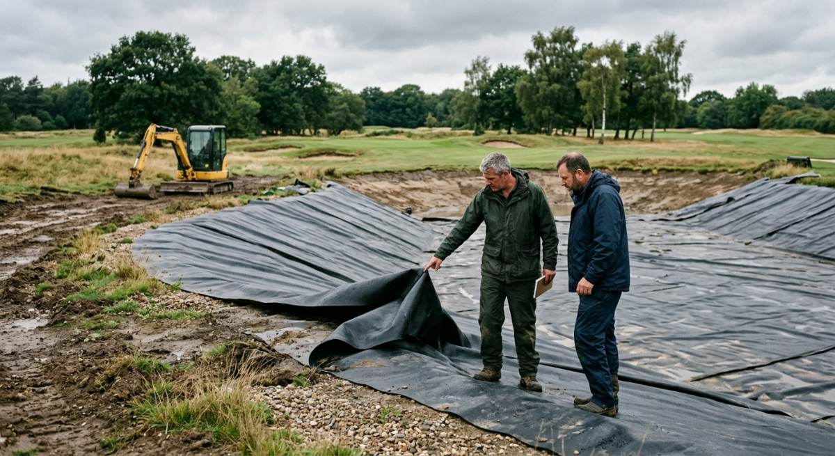
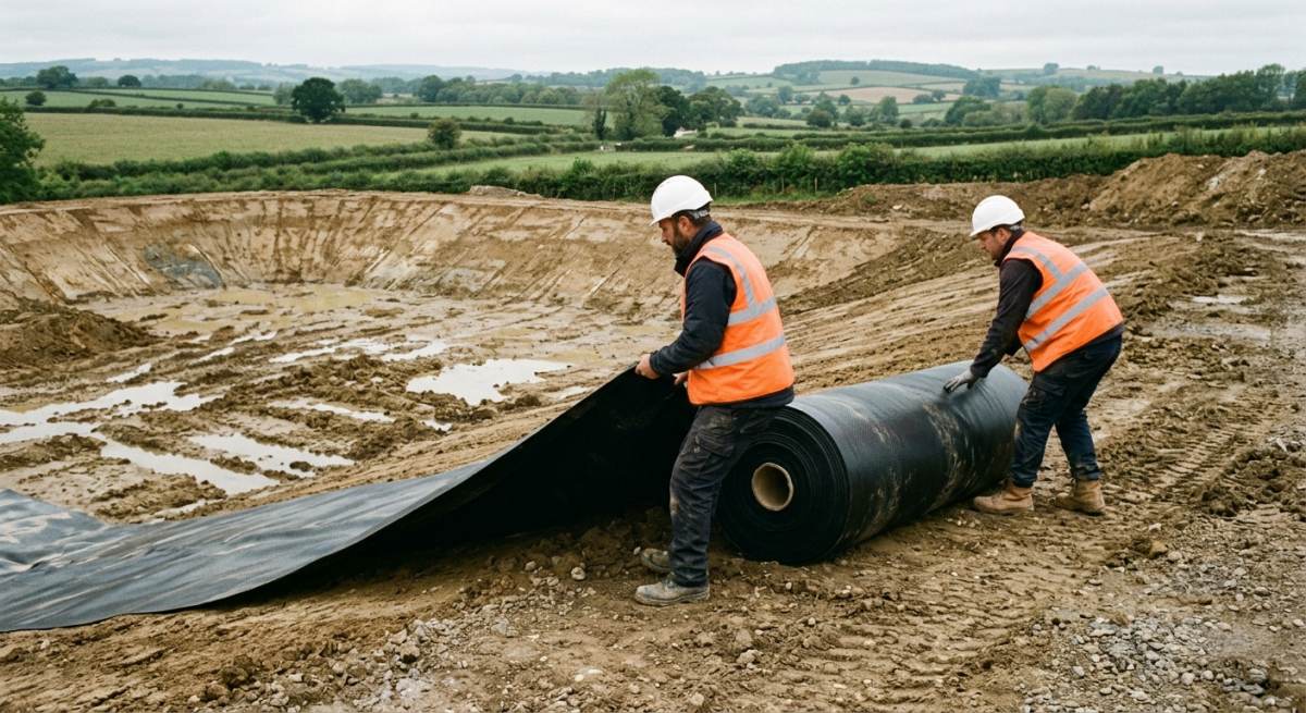
Getting the lining specification right is the single most important factor when designing an underground attenuation tank. CIRIA C753 underlines that a failing membrane compromises the structural integrity of the surrounding ground and can lead to unmanaged pollution runoff into local waterways.
Choosing between standard geomembranes and specialist gas barriers
Selecting the correct barrier material depends entirely on the ground conditions and site contamination profile uncovered during your initial desk study. You must assess whether the system needs to retain stormwater purely, or keep hazardous ground gases out of the attenuation structure.
When dealing with clean greenfield sites, heavy-duty polypropylene or standard high-density polyethylene Geomembranes often provide a robust and cost-effective seal. However, on brownfield developments, traditional liners are rarely sufficient on their own. In these environments, integrating specialist Gas Barrier Membranes is essential to block dangerous substances like methane, carbon dioxide, or volatile organic compounds from entering the tank and migrating into adjacent streets.
Ensuring leak-free performance with welded impermeable liners
Site-welded joints deliver superior joint strength compared to simple taped overlaps when creating a watertight seal around crate systems. Taped seams can easily degrade under constant hydrostatic pressure, making dual-track thermal welding the professional benchmark across the industry.
To achieve a long-term, fail-safe installation on site, specialist installers typically follow a strict 3-step quality assurance routine.
- Prepare and align the structural panels with clean, dry overlaps before bringing the self-propelled hot wedge welding equipment into position.
- Form twin parallel welds across all panel joints, leaving an uninterrupted central channel specifically designed for low-pressure air testing.
- Hook up a calibrated pressure gauge to inflate the test channel, verifying that zero pressure drops occur across the entire seam over a 5-minute period.
By strictly adhering to this rigorous testing routine, engineers ensure that Welded Impermeable Liners maintain absolute integrity throughout their multi-decade design life.
Safeguarding structural integrity with protective geotextiles
Thick non-woven fleece layers must be specified to shield the primary impermeable membrane from continuous physical puncture risks. Sharp angular aggregates in the surrounding backfill and pressure points from the internal plastic crates will easily damage unarmoured liners during soil compaction.
Engineers routinely sandwich the primary waterproof membrane between two layers of heavy-duty Protective Geotextiles. The bottom cushioning layer absorbs ground movement and smooths out irregularities in the prepared sand formation bed. Meanwhile, the top layer acts as a sacrificial cushion that neutralises point-load stress from the modular plastic crates. This dual-layer approach provides complete peace of mind, ensuring the core waterproof core stays completely intact despite heavy traffic loads on the surface above.
Long Term Maintenance and Asset Protection
Minimising Silt Accumulation Through Smarter Tank Geometry
Silt accumulation remains the single greatest threat to attenuation capacity in below-ground storm drainage networks. Designing systems with dedicated sediment forebays and smooth internal channels ensures that heavy solids settle safely before reaching the main storage volume.
Without proactive design choices, fine sediment quickly settles across the tank floor, reducing storage capacity and causing localised blockages. The CIRIA C753 SuDS Manual emphasizes that effective asset protection begins at the drawing board. By specifying high-performance geotextile wrappings and integrated silt traps, engineers can dramatically extend the operational lifespan of the installation.
To keep sediment levels under control throughout the lifespan of the tank, installers should follow a clear 3-step routine.
- Inspect upstream catchpits and silt traps every 6 months to remove trapped debris.
- Monitor inlet channels after major storm events to check for unusual gravel build-up.
- Flush silt interceptors annually using high-pressure water jets to maintain peak flow rates.
Designing Safe CCTV Inspection Access for Long-Term Monitoring
Providing clear CCTV Inspection Access is fundamental to evaluating internal structural health without invasive excavation. Incorporating strategically placed access shafts allows maintenance teams to deploy remote cameras and identify potential issues early.
Gaining visibility inside a subterranean geocellular tank can prove challenging if access points are treated as an afterthought. Modern CIRIA guidelines require dedicated vertical risers aligned perfectly with internal inspection corridors. This setup allows technicians to survey structural integrity, check for crushed cells, and verify that sediment traps are functioning as intended.
Standard maintenance access layouts typically feature three core components:
- Large-diameter inspection shafts positioned directly over main distribution pipes.
- Open-bore camera channels that allow unobstructed horizontal camera travel.
- Heavy-duty access covers rated for high-load traffic zones at ground level.
Developing a Robust SuDS Maintenance Plan for Sustainable Operation
A comprehensive SuDS Maintenance Plan turns theoretical design principles into practical, day-to-day asset management. Establishing a structured schedule guarantees that routine checks occur systematically, protecting the original engineering investment.
Ad-hoc repairs often lead to premature asset failure and expensive emergency interventions. A well-structured regime outlines precise tasks, clear responsibilities, and mandatory reporting frequencies for site operators. This documentation proves invaluable when handing over adoption responsibilities to local water authorities or private management entities.
Aligning Structural Integrity With the Intended Design Life
An attenuation system must maintain its structural integrity for a minimum Design Life of 50 to 100 years. Specifying high-quality, chemically resistant polymers prevents premature degradation caused by aggressive soil conditions or contaminated runoff.
Achieving long-term performance requires careful calculation of lateral ground pressure, traffic loading, and deep-burial stresses. Catalogue Engineering brings over 30 years of specialist installation experience to ensure every gas barrier and water management system meets these exacting standards. Correct installation techniques prevent structural deflection, guaranteeing that subterranean assets remain fully functional for generations to come.
Frequently Asked Questions around Attenuation Tank
What Is An Attenuation Tank And How Does It Work?
An attenuation tank is an underground storage system designed to hold excess stormwater during heavy rainfall. It collects surface runoff from roofs, driveways, and roads, storing it temporarily before releasing it slowly into the local drainage network or watercourse.
By controlling the outflow rate, the tank prevents downstream sewers from becoming overwhelmed. This managed approach protects local communities from flash flooding while ensuring the drainage infrastructure copes with extreme weather events.
Why Are CIRIA C753 Guidelines Important For Attenuation Tank Design?
The CIRIA C753 SuDS Manual provides the essential industry standard for designing safe, sustainable, and durable attenuation tanks in the UK. It sets out the exact engineering calculations and environmental principles required to manage surface water effectively.
Following these guidelines ensures that your drainage design meets strict local authority standards and regulatory requirements. It helps engineers balance hydraulic capacity, structural strength, and water quality treatment in a single, well-planned system.
What Materials Are Typically Used To Build An Attenuation Tank?
Modern attenuation tanks are most commonly constructed using modular plastic geocellular crates, precast concrete chambers, or large-diameter plastic pipes. The choice of material usually depends on the ground conditions, available space, and the expected traffic loads above the site.
Geocellular crates are particularly popular because they are lightweight, easy to transport, and quick to assemble on site. However, precast concrete is often preferred for deeper installations or where very heavy vehicle traffic is expected overhead.
How Big Does An Attenuation Tank Need To Be?
The size of an attenuation tank depends entirely on the size of your site, the area of impermeable surfaces, and local rainfall predictions. Engineers calculate the required storage volume based on a 1 in 100-year storm event, whilst adding a standard allowance for climate change.
Local lead local flood authorities typically specify the maximum allowable discharge rate for your site. Once this greenfield runoff rate is set, the tank must be large enough to hold all the surplus water that cannot be discharged immediately.
Do Attenuation Tanks Provide Water Quality Treatment?
Attenuation tanks can provide water quality treatment, but only if they are designed with appropriate silt traps, oil separators, or geotextile filters. The CIRIA C753 manual strongly emphasises treating runoff at source to remove pollutants before stormwater enters the main storage area.
Without proper upstream treatment, sediment and hydrocarbons will settle inside the tank and reduce its storage capacity over time. Integrating effective filtration protects both the performance of the tank and the surrounding environment.
Where Should An Attenuation Tank Be Installed On Site?
An attenuation tank is usually installed beneath non-buildable outdoor spaces such as car parks, soft landscaped areas, or internal access roads. Placing the tank at a low point on the site allows surface water to flow naturally into the system using gravity.
Engineers must also consider subterranean utilities, soil strength, and high groundwater levels when choosing a location. Placing the tank too close to building foundations or heavy structural loads can complicate the installation and increase structural costs.
How Do You Maintain An Attenuation Tank Properly?
Regular maintenance involves inspecting upstream silt traps, catchpits, and flow control chambers at least twice a year. Removing accumulated silt and debris from these access points stops blockages from forming and keeps the system working efficiently.
The main storage tank should also undergo a visual or camera inspection every 1 to 2 years to check for structural damage or sediment build up. Keeping detailed maintenance logs is often a legal requirement for adopting authorities and management companies.
How Long Does A Typical Attenuation Tank Last?
A high quality, properly installed attenuation tank will easily last between 50 and 100 years. The structural plastics and concrete units used in modern manufacturing are designed to withstand heavy soil pressure and ground movement over long periods.
The actual lifespan of your system relies heavily on consistent routine maintenance. Protecting the tank from silt accumulation and chemical contamination ensures the structural integrity remains uncompromised for decades.
What Is The Difference Between Attenuation Tanks And Retention Tanks?
An attenuation tank holds stormwater temporarily and empties completely once the rainfall event passes, whereas a retention tank keeps a permanent pool of water at all times. Attenuation systems focus strictly on flood prevention by controlling discharge rates into sewers.
Retention systems, on the other hand, are often used for rainwater harvesting or creating wetland habitats. While both manage surface water, attenuation tanks are far more common on commercial and residential developments with limited space.
How Much Does It Cost To Install An Attenuation Tank?
The total cost of an attenuation tank installation varies widely depending on the storage volume, site accessibility, and ground conditions. Small commercial systems might start around £10,000, while large-scale residential drainage projects can easily exceed £100,000.
You must also factor in the costs of excavation, ground preparation, membrane lining, and backfilling materials. Working closely with an experienced drainage engineer early in the design process helps optimise the tank volume and keep overall construction costs down.
Ready to Discuss Your Attenuation Tank Project?
Get in touch with our specialists today for detailed site guidance, technical specifications, and a quotation tailored to your requirements.