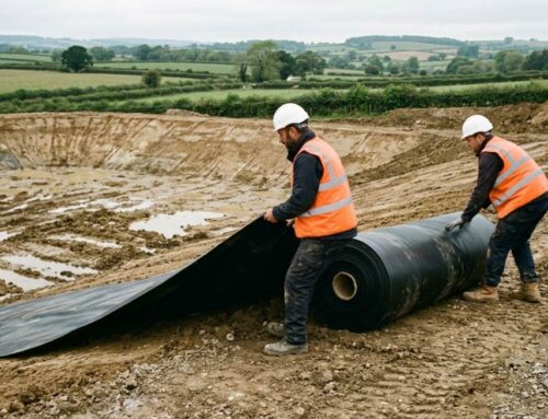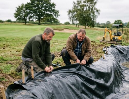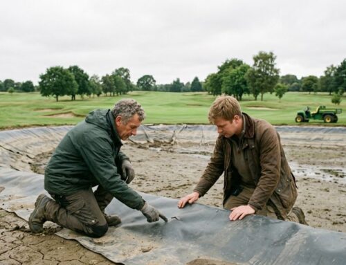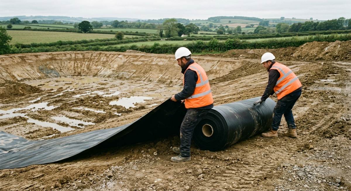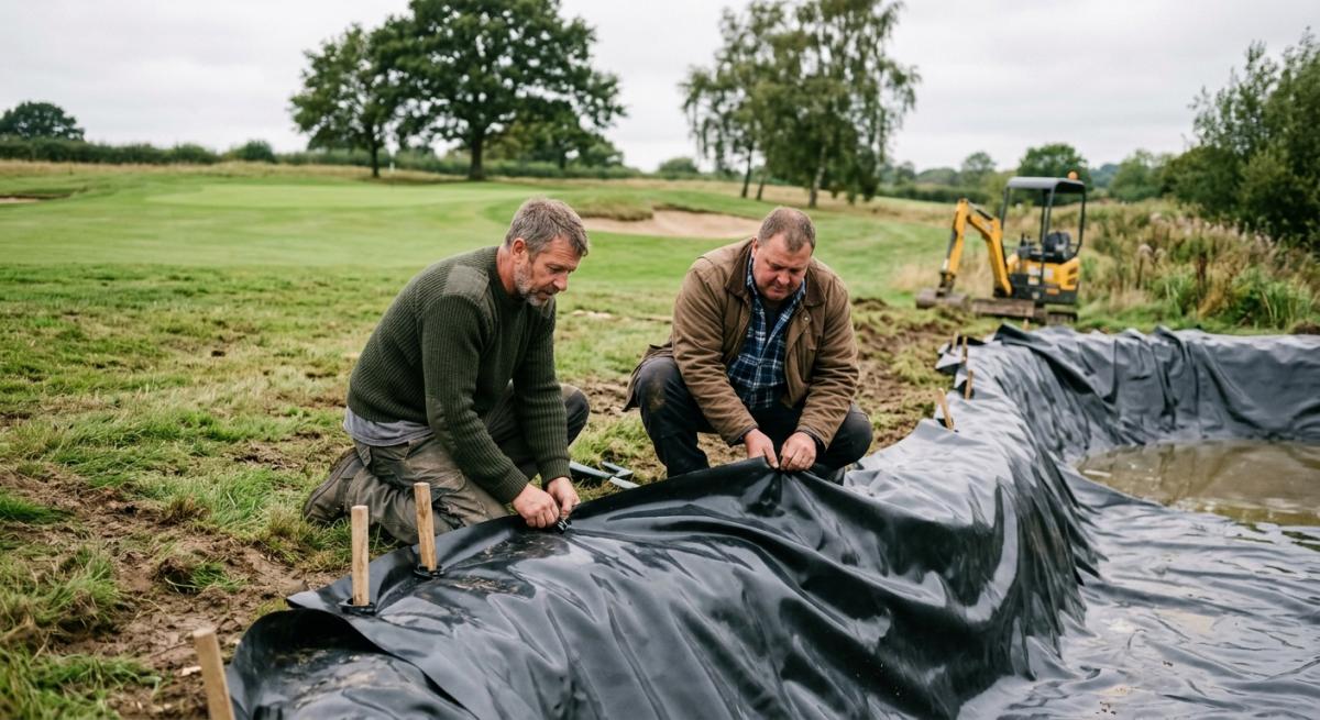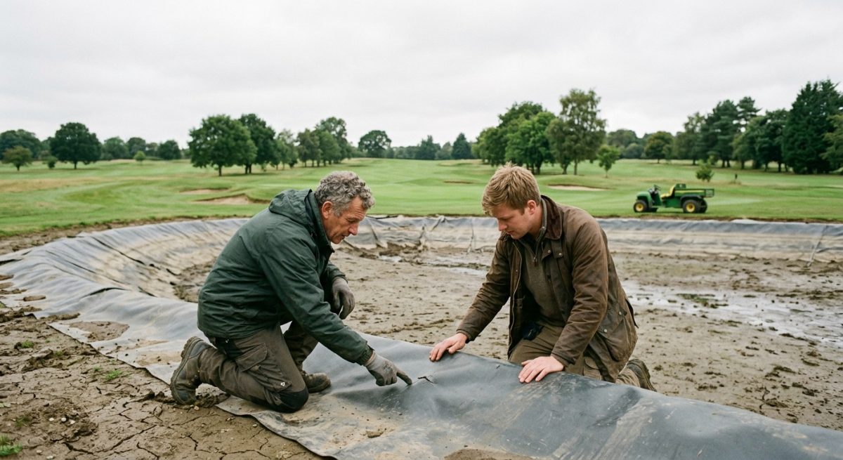
Designing resilient Sustainable Drainage Systems across modern built-up areas requires a clear understanding of sub-surface water management and soil mechanics. Surface water run-off from intense 1 in 100-year storm events poses severe flooding risks to nearby infrastructure if development plans lack robust control measures. Attenuation Tanks sit at the centre of these surface management strategies, holding excess storm water temporarily before releasing it into local watercourses or sewer networks at a controlled greenfield rate. To function effectively without undermining adjacent building foundations or contaminating surrounding ground conditions, these modular underground crate systems rely on impermeable barriers.
Specifying the correct Geomembranes alongside high-performance geotextile wrappings protects the installation against puncture risks, structural settlement, and unwanted water ingress or egress. This detailed technical guide covers fundamental principles of attenuation design, evaluating how specialist membrane selection influences 60-year design life compliance, site safety, and overall structural performance.
Managing rapid surface water run-off across crowded city centres and high-density housing developments presents severe technical challenges for modern civil engineers and commercial property developers. Balancing peak storm flows while satisfying strict local planning authority conditions demands precise sub-surface volume calculations, robust structural crate selection, and completely dependable water containment solutions.
Failure to encapsulate modular attenuation units properly causes catastrophic soil erosion, localised ground subsidence beneath adjacent roads, and immediate planning enforcement actions. According to CIRIA C753 guidance, poor membrane selection and inadequate joint sealing account for up to 45% of early sub-surface drainage failures recorded across commercial UK construction sites.
Deploying durable high-density Geomembranes alongside heavy-duty non-woven geotextile fleece layers creates an impermeable, fully sealed underground reservoir that manages peak rainfall reliably. This double-layer engineered wrapping shields the structural core from sharp aggregate punctures while ensuring 100% water retention until controlled discharge occurs through specified flow-control chambers.
KEY TAKEAWAYS
- Attenuation Tanks temporarily store large volumes of surface water during extreme weather events to protect local streets and built-up areas from dangerous flash flooding.
- High-grade Geomembranes form an essential impermeable barrier around subterranean crate modules, preventing uncontrolled storm water exfiltration into sensitive sub-base soils.
- Sustainable Drainage Systems require tailored non-woven geotextile protection fleeces wrapped around outer membranes to absorb impact forces and prevent puncture damage during aggregate backfilling.
Table of Contents
- Criteria for Choosing Geotextile Protection Layers
- Selecting Impermeable Geomembranes for Water Retention and Gas Protection
- Jointing Techniques and Quality Assurance during Installation
- Site Conditions and Chemical Compatibility Considerations
- Frequently Asked Questions around Attenuation Tank Design
Need Specialist Advice on attenuation tank design?
Speak to our technical team today for tailored specifications, regulations compliance, and practical support.
Criteria for Choosing Geotextile Protection Layers
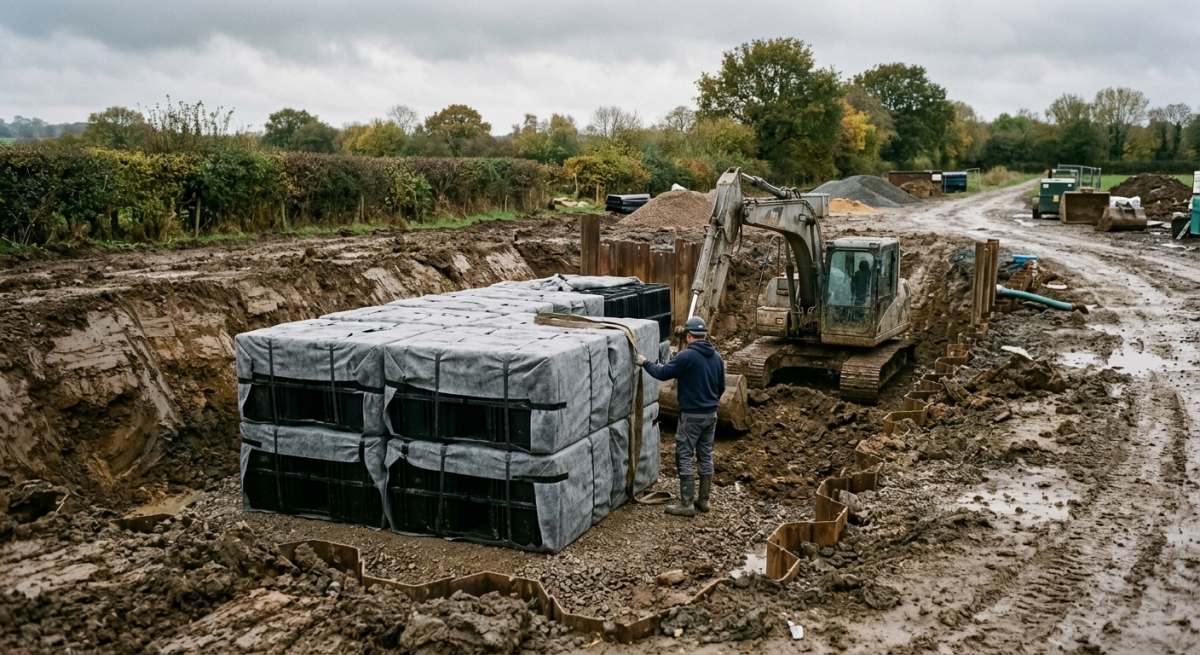
Selecting the correct protective fleece is essential to protect impermeable geomembranes from puncture damage during installation and throughout their 60-year lifespan. Without a suitable buffer, sharp angular aggregates and structural loads will breach the membrane, causing costly leaks beneath built-up area developments. Careful evaluation of fabric weight, polymer type, and mechanical strength prevents pre-construction damage and long-term environmental degradation.
Assessing Subgrade Conditions and Puncture Resistance
Selecting an appropriate non-woven fleece depends directly on evaluating the surrounding ground before laying any membrane. Poorly prepped ground with sharp aggregate demands higher CBR Puncture Resistance to prevent catastrophic tears.
Engineers must assess site-specific Subgrade Conditions, taking into account soil compaction, grain size, and water table fluctuations. Highly variable soils containing crushed concrete or coarse gravel require heavy-duty fabrics rated above 3000 N static puncture resistance. Conversely, smooth clay foundations in quiet residential towns may only need light 150 g/m² protective cushions. Calculating these physical demands beforehand ensures the primary membrane remains entirely intact during backfilling and compaction operations.
Evaluating Non Woven Manufacturing and Tensile Strength
A heavy-duty Needle Punched Geotextile provides the superior cushioning necessary to safeguard sensitive impermeable liners against point loads. The continuous filament structure absorbs localised stress while maintaining long-term hydraulic permeability.
Mechanically bonded virgin polypropylene fibres create a robust protective matrix that resists chemical degradation in acidic groundwater. A premium Needle Punched Geotextile exhibits high dynamic cone drop resistance, protecting the attenuation modules when workers install backfill materials. Using recycled or thermally bonded alternatives often risks brittle tearing under heavy vehicle loads on local streets overhead. Specifiers must compare dynamic penetration ratings alongside grab tensile strength to optimise protection against harsh site handling and ongoing traffic weight.
Implementing Field Inspection and Verification Protocols
Rigorous site inspections ensure protection fleeces perform as intended during backfilling and operational cycles. Engineers must verify seam overlaps and material integrity before placing surrounding aggregate.
To guarantee full protective coverage across the entire tank footprint, follow this straightforward 3-step verification process on site
- Inspect the underlying formation for sharp debris and rock projections, ensuring proper trench preparation before unrolling geotextile rolls.
- Check that all adjacent fleece sheets achieve a minimum 300 mm overlap or are thermally joined along continuous seams to eliminate gaps.
- Perform visual checks for snags, UV exposure damage, or fabric displacement before placing structural attenuation crates onto the membrane assembly.
Proper execution of these steps preserves structural integrity, preventing sub-surface failures across demanding commercial attenuation schemes.
Technical Specification ComparisonSwipe sideways to view full table →
| Specification | Primary Features | Lifespan | Cost Bracket | Compliance |
|---|---|---|---|---|
| 1.0mm Flexible Polypropylene (PP) Geomembrane with 300gsm Protection Fleece | Fully welded impermeable barrier, excellent puncture resistance, highly flexible for crate tank encapsulation | 100 years | ££ | Building Regs Part H3, CIRIA C753, BS EN 13361, BBA Certified |
| 1.5mm High-Density Polyethylene (HDPE) Geomembrane with 500gsm Protection Fleece | Superior chemical and hydrocarbon resistance, high tensile strength, ideal for contaminated brownfield sites | 100 years | £££ | Building Regs Part H3, CIRIA C753, BS EN 13492, BBA Certified |
| 150gsm Non-Woven Needle-Punched Polypropylene Geotextile Jacket | Permeable filter wrap for infiltration soakaway systems, prevents silt ingress while allowing free water flow | 50 years | £ | Building Regs Part H3, CIRIA C753, BS EN 13252 |
| Sodium Bentonite Geosynthetic Clay Liner (GCL) with PE Lamination | Self-sealing active clay barrier, robust performance under heavy overburden loads and high groundwater levels | 100 years | ££££ | Building Regs Part H3, CIRIA C753, BS EN 13361 |
Selecting Impermeable Geomembranes for Water Retention and Gas Protection
Material Selection for Sub-Surface Water Retention
Choosing the correct polymer lining prevents unmanaged stormwater losses and protects sub-surface ground structures from long-term hydraulic pressure. Engineers typically select a Polypropylene Geomembrane or a High Density Polyethylene liner depending on site-specific flexibility requirements and chemical exposure risks.
For modular crate systems in tight town centre excavations, a flexible Polypropylene Geomembrane offers superior conformability around sharp corners and intricate pipe penetrations. This flexibility reduces stress concentration on factory seams and speeds up installation in complex underground tanks. Conversely, High Density Polyethylene delivers exceptional chemical resistance, making it the preferred option when managing polluted runoff from industrial estates or busy local streets where petrol, grey diesel, and heavy oils might accumulate.
Selecting membranes with high stress-crack resistance prevents unexpected material failures during seasonal ground movement. Standard retention installations use liners with a minimum thickness of 1 mm to 1.5 mm to withstand puncture loads during backfilling operations.
Integrating Methane and Radon Gas Protection
Attenuation tanks installed on brownfield sites require a specialised Gas Barrier Membrane to block dangerous ground gases from entering the drainage structure. Installing a multi-layer composite barrier ensures both total water tightness and compliance with BS 8485 gas protection standards.
When attenuation crates sit within contaminated ground, volatile organic compounds, methane, and radon pose severe risks to adjacent buildings in built-up areas. An effective Gas Barrier Membrane combines an aluminium foil core with robust polyolefin protective layers, creating a continuous seal against soil contaminants and pressurised ground gas.
This dual-capability lining eliminates the need for separate gas and water barriers, lowering material costs by up to 20% while saving time during subterranean works. Site assessors should always cross-reference ground gas risk assessments with local authority requirements before specifying membrane thickness. Designers must verify that the chosen membrane carries independent certification for both hydrocarbon resistance and hydrostatic head retention up to 5 metres deep.
On-Site Jointing and Quality Control Protocols
Field-welding techniques must create continuous, high-integrity seams across the entire footprint of the attenuation crate assembly. Rigorous non-destructive testing validates these joints to guarantee zero leakage throughout a 60-year service life.
To achieve continuous containment across large sub-surface attenuation projects, site teams must follow a strict jointing procedure under controlled environmental conditions.
- Prepare and clean all membrane edges to maintain a consistent 100 mm overlap across every joint line.
- Execute double-wedge thermal welding along the seam length to melt and fuse adjacent polymer sheets into a single homogenous layer.
- Conduct spark testing or air-pressure testing on the central channel at 2 bar for 5 minutes to confirm absolute seam integrity before backfilling.
Jointing Techniques and Quality Assurance during Installation
Thermal Welding Procedures for Geomembranes
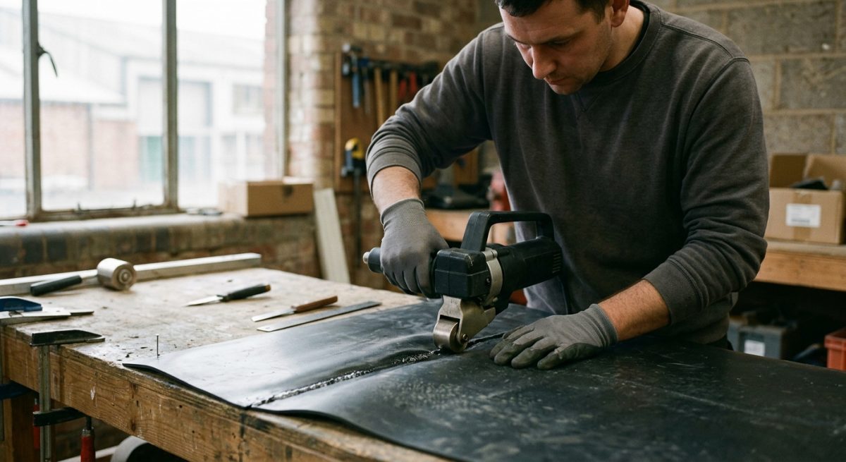
Double Wedge Welding serves as the primary technique for joining continuous geomembrane sheets in sub-surface attenuation tank installations. This method creates a double-track seam with an enclosed air channel that allows rapid pressure testing across long runs.
For complex details, patch repairs, and pipe penetrations, installers deploy Extrusion Welding to bond polymer panels securely. This secondary method forces a molten polymer bead along prepared edges, guaranteeing a watertight seal around intricate corners where automated wedge machines cannot operate. Proper surface preparation requires abrading the seam area within 20 minutes prior to welding to remove oxidation layers and ensure optimal fusion between parent sheets.
To achieve a high-quality seam on site, installation crews follow a 3-step welding sequence.
- Clean and prepare geomembrane overlaps by removing all moisture, fine silt, and organic debris.
- Calibrate welding machinery temperature, nip roller pressure, and track speed based on ambient air conditions.
- Run continuous thermal seams while maintaining a consistent 100 mm minimum overlap across every panel line.
Non-Destructive Seam Integrity Testing
Field testing verifies that every joint within the membrane envelope meets strict zero-leakage standards before tank backfilling occurs. Technicians use air channel testing for double seams and vacuum box testing for detail welds to catch minor flaws early.
Air channel testing involves sealing both ends of the double-wedge seam, inflating the central cavity to 200 kPa, and monitoring pressure drop over a 5-minute duration. A steady pressure reading confirms a continuous seal along
Site Conditions and Chemical Compatibility Considerations
Assessing Soil Chemistry and Geotechnical Factors
Site-specific Soil Chemistry dictates the long-term durability of geomembrane and geotextile wraps surrounding sub-surface attenuation tanks. Soil pH levels, sulfate concentrations, and heavy hydrocarbon contaminants directly alter polymer integrity over a 60-year design life.
Ground conditions vary across every UK development site, ranging from highly acidic peats to aggressive alkaline clays. Ground investigation reports must highlight aggressive soil contaminants that embrittle standard geomembranes over time. Where aggressive soil chemistry exists, engineers specify high-grade polypropylene or high-density polyethylene membranes paired with heavy-duty non-woven geotextile protection layers.
This dual-layer strategy prevents sharp aggregate inclusions in coarse backfill from piercing the impermeable barrier during mechanical compaction. Designers must also evaluate soil bearing capacity at depths from 1 metre to 6 metres to ensure structural stability beneath heavily trafficked sites.
Managing Water Table Level and Hydrostatic Pressure
A high Water Table Level exerts continuous hydrostatic pressure that risks floating or collapsing under-specified attenuation modular crates. Engineers must specify robust impermeable geomembranes alongside heavy-duty protective geotextiles to prevent unwanted groundwater ingress and structural displacement.
In areas with high groundwater levels, civil engineering contractors must execute a rigorous 3-step pre-installation verification routine.
- Conduct 7-day continuous groundwater monitoring to establish maximum seasonal water heights.
- Calculate buoyancy uplift forces against total dead loads prior to backfilling operations.
- Install a continuous 300 g/m² non-woven geotextile cushion layer below the geomembrane to prevent sharp ballast puncture.
Ignoring seasonal water table variations frequently leads to compromised attenuation capacity or catastrophic liner uplift. Selecting heavy-duty flexible membranes with double-welded seams ensures structural integrity against fluctuating hydrostatic head pressure in low-lying coastal regions and flood-prone river basins.
Evaluating Chemical Resistance for Surface Runoff
Specifying liners with proven Chemical Resistance protects stormwater attenuation systems from aggressive surface runoff containing de-icing salts, fuels, and industrial solvents. Polypropylene and high-density polyethylene membranes resist chemical degradation far better than standard options in polluted built-up areas.
Runoff collected from local streets, commercial carparks, and industrial estates carries trace hydrocarbons, heavy metals, and chemical pollutants. Over extended operational cycles, exposure to oils and de-icing salts breaks down inferior polymers, causing micro-cracking and structural failure. Designers must verify that chosen geomembranes carry full chemical compatibility certification for expected site pollutants.
Pairing chemically resistant geomembranes with heavy needle-punched non-woven geotextiles creates a durable sub-surface barrier. This configuration safely detains polluted stormwater while ensuring 100% containment without leaching toxic compounds into surrounding groundwater reserves.
Frequently Asked Questions around Attenuation Tank Design
What Is the Main Purpose of an Attenuation Tank Design?
An attenuation tank design aims to collect excess stormwater run-off and release it into local drainage networks at a controlled rate. By storing heavy rainfall during peak storms, these sub-surface structures prevent downstream flooding and reduce pressure on public sewers in town and city environments.
The design usually incorporates plastic geocellular crates or oversized pipes wrapped in specialised geotextiles or impermeable geomembranes. Engineers calculate the required storage volume based on local storm data for a 1-in-100-year rainfall event, plus an extra 40% allowance for climate change.
How Do You Choose Between a Sealed Geomembrane and a Permeable Geotextile?
You must select a sealed geomembrane when you need to prevent water from leaking into the surrounding soil, or to stop contaminated groundwater from entering the tank. In contrast, a permeable geotextile fleece is used when the soil conditions allow stormwater to soak back into the ground safely through infiltration.
If your site has a high groundwater table or contaminated land, an impermeable 1-mm polypropylene or high-density polyethylene geomembrane is compulsory. For clean sites with good soil drainage, a simple non-woven geotextile wrap provides a cost-effective solution that filters out fine silt while allowing natural soakaway.
What Is the Typical Lifespan of a Sub-surface Attenuation Tank Membrane?
A high-quality geomembrane or geotextile wrapping has a target design lifespan of at least 60 years when correctly installed underground. This long-term durability matches the standard design life of modern commercial buildings and residential developments.
To achieve this 60-year working life, installers must protect the primary liner from mechanical damage using heavy-duty protective fleece layers. Exposing membranes to direct sunlight for more than 14 days during construction can cause ultraviolet damage, so rapid backfilling is essential.
How Does High Groundwater Affect Attenuation Tank Design?
High groundwater levels create hydrostatic uplift pressure that can float or crush an empty attenuation tank, meaning designers must anchor the structure or use an impermeable membrane enclosure. When groundwater sits above the base of the tank, a fully welded 1.5-mm geomembrane is needed to keep outside water out.
Engineers calculate flotation risks by comparing the overall weight of the soil overburden against the buoyancy force of 100% saturated ground. Adding a 300-mm layer of compacted aggregate over the top geotextile wrap usually supplies enough dead weight to stabilize the structure.
What Geotextile Grade Is Needed to Protect the Inner Membrane?
A non-woven needle-punched geotextile fleece with a minimum mass of 300 g per square metre is recommended to protect impermeable geomembranes from sharp stones. This protective layer acts as a soft cushion between the hard modular crates and the surrounding backfill material.
In soils with sharp aggregate or crushed rock, engineers often increase this specification to a 500-g protective fleece. Using a lower grade fleece risks puncture damage during backfilling, which could compromise the 100% water-tight seal of the system.
How Do Traffic Loads Impact Attenuation Tank Design?
Heavy vehicle loads demand higher vertical compressive strength from the internal geocellular units and require a deeper cover depth above the tank geotextile. For car parks with delivery vehicles, tanks typically require a minimum cover depth of 1 to 1.5 metres of well-compacted material.
If a tank is placed under a pedestrian walkway, a cover depth of 0.5 metres is often enough. Structural calculations must account for both long-term dead loads from the earth and short-term live loads from 44-tonne heavy goods vehicles.
Why Is Joint Testing Essential During Membrane Installation?
Joint testing ensures every thermal weld in the geomembrane layer is completely water-tight and structural before backfilling begins. Unsealed seams lead to underground leaks, which can soften sub-base soil and cause ground settlement under paved surfaces.
Technicians use double-seam wedge welding along with air-pressure testing at 2 bar for 5 minutes to verify joint integrity. Every single field seam must undergo 100% non-destructive testing, and test logs should form part of the final site sign-off documentation.
Can an Attenuation Tank Be Combined with a Rainwater-harvesting System?
Yes, you can design a dual-purpose attenuation tank by using a fully sealed geomembrane and adding a permanent water-storage zone in the bottom section. This hybrid arrangement holds a fixed volume of water for flushing toilets or watering green spaces, while the top volume remains empty for storm attenuation.
A lower suction pipe extracts clean water, while an upper overflow pipe controls discharge rates during heavy rain. Using 1 tank for 2 jobs reduces excavation costs and optimizes land use on tight development sites.
How Do You Prevent Sediment Build-up in an Attenuation Tank?
You prevent sediment accumulation by placing pre-treatment devices, such as catchpits and silt traps, upstream of the main tank inlet. These chamber units catch fine sand, leaves, and grey mud before stormwater reaches the wrapped crate core.
Additionally, wrapping the outer perimeter in a non-woven geotextile filter fabric prevents surrounding soil particles from entering through the crate walls. Annual inspection of upstream catchpits ensures the system maintains 100% storage capacity over its 60-year lifespan.
What Are the Most Common Failures in Attenuation Tank Wraps?
The most frequent failures occur when sharp backfill punctures the geotextile lining or when site workers fail to weld geomembrane seams correctly. Punctures allow soil silt to enter and clog the tank, which reduces its total holding capacity over time.
Another common issue is inadequate compaction of side-fill material, which allows the geocellular crates to shift and tear the outer fleece. Following strict installation guidance and using 300-mm layer compaction steps prevents 95% of these field-based failures.
Ready to Discuss Your attenuation tank design Project?
Get in touch with our specialists today for detailed site guidance, technical specifications, and a quotation tailored to your requirements.